Pelco Dx8000 User Manual
Page 21
C623M-C (3/05)
21
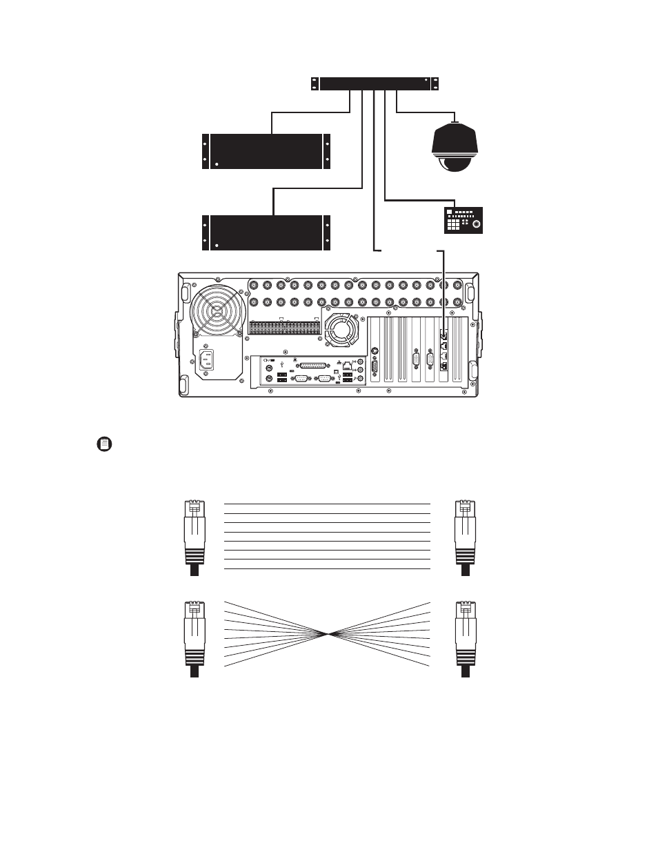
Figure 11. RS-422/RS-485 Configuration Example 2
Figure 12. Cable Wiring Schemes
NOTE: Different types of devices may require alternative cable wiring schemes. Wiring schemes commonly used by Pelco products include
straight and rollover types. Refer to the documentation included with your PTZ device to ensure that cables and connectors are wired
appropriately. Figure 12 illustrates straight and rollover cable wiring schemes
KBD300A
PTZ
1-16
IN1
IN2
IN3
IN4
IN5
IN6
IN7
IN8
IN9
IN10
IN11
IN12
IN13
IN14
IN15
IN16
OUT16
OUT15
OUT14
OUT13
OUT12
OUT11
OUT10
OUT9
OUT8
OUT7
OUT6
OUT5
OUT4
OUT3
OUT2
OUT1
ALARM INPUTS
RELAY OUTPUTS
1
2 2 4 5 6 7 8 GND
9 10 11 12 13 14 15 16
1
2 2 4 5 6 7 8 GND
9 10 11 12 13 14 15 16
CRT
CM9760-DMR
CM6800
CM6800
ROLLOVER CABLE
PIN
1
2
3
4
5
6
7
8
PIN
1
2
3
4
5
6
7
8
PIN
1
2
3
4
5
6
7
8
PIN
1
2
3
4
5
6
7
8
RJ-45
STRAIGHT CABLE
ROLLOVER CABLE
RJ-45
RJ-45
RJ-45