Quickdraw, Boiler water heater – PVI Industries QUICKDRAW PV500-26 User Manual
Page 8
QUICKDRAW
Boiler Water Heater
8
PV500-26 06/12
5.2
Filling the Unit
1. Fill the system with water. To be sure that the unit is not “air bound,” open the relief valve. Leave the valve open
until a steady flow of water is observed. Close valve and complete filling the system.
2. In hard water areas, potable water treatment should be used to reduce introduction of minerals into the system.
Minerals in the water can collect on the tubes and heat-exchanger surfaces reducing the life of the product.
Heat exchanger failure due to scale accumulation is not covered by the product warranty.
3. Make sure there are no system leaks. DO NOT use petroleum based stop-leak products. All system leaks must
be repaired.
5.3
Relief Valve Piping
The water heater is supplied with a pressure and temperature relief valve, sized in accordance with ASME
requirements. Each relief valve should be piped to a suitable floor drain. No reducing coupling or other restriction
can be installed in the discharge line. It is strongly recommended that this valve should be manually operating at
least once a year.
WARNING: Secure the relief valve pipe to a suitable floor drain such that very hot water does not openly
splash during a significant relief valve discharge. If the relief valve pipe is not routed and secured to a
suitable drain, hot water discharge can result in property damage, scalding and personal injury or loss of
life.
5.4
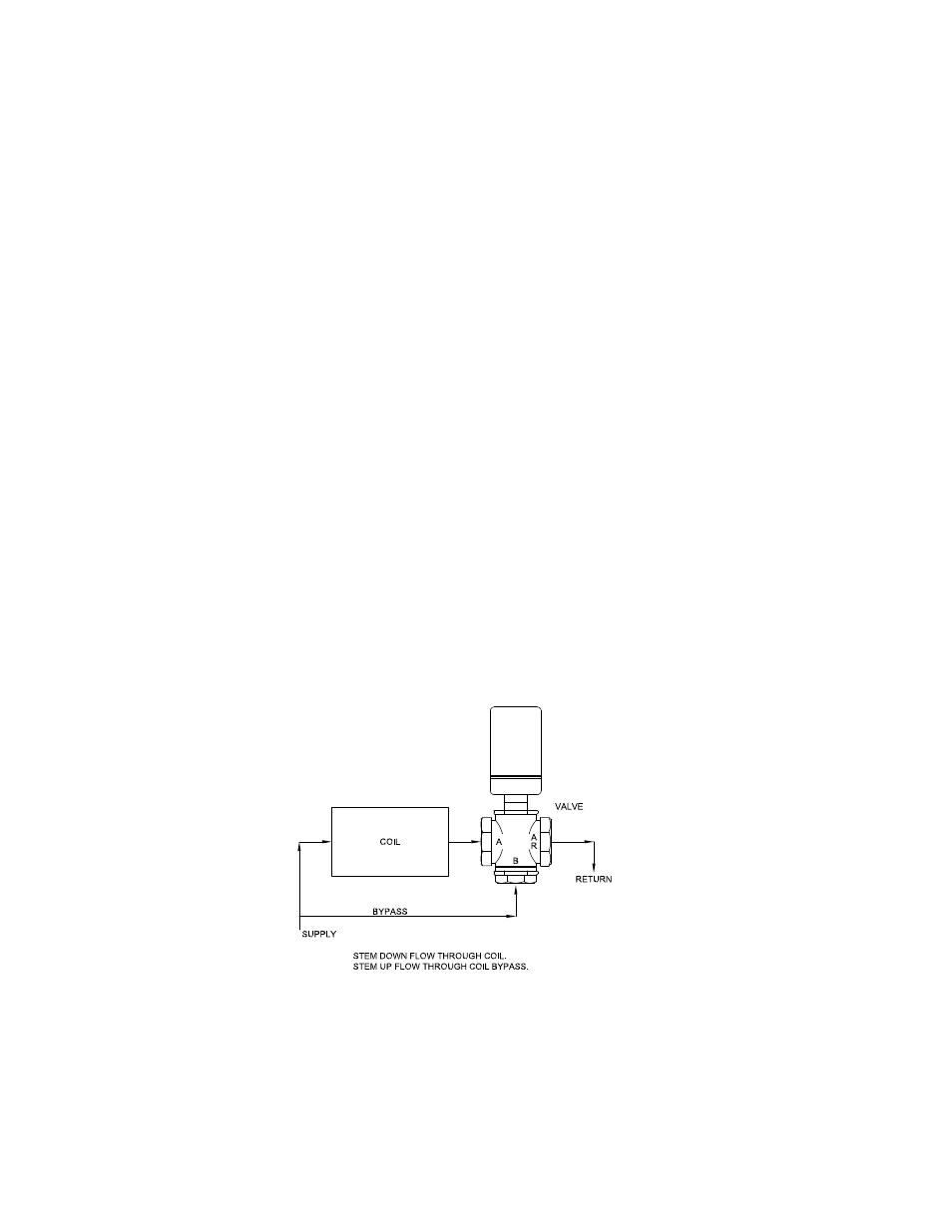
Sequence of Operation
(Refer to figure below)
1. When power is supplied through the unit’s On-Off switch, if the stored water temperature is below the operating
thermostat set point, the limit operating circuit closes creating a call-for-heat-demand, which energizes the
actuator on the three-way mixing valve.
2. The three-way mixing valve returns circulating boiler water to the boiler supply loop through its bypass ports.
On a call-for heat, the actuator motor runs and the actuator shaft extends causing the valve to divert the boiler
water through the heat exchanger before it is returned to the boiler supply loop.
3. When the demand is satisfied, the limit operating circuit opens and the valve actuator is de-energized. The
actuator motor stops running and the actuator shaft spring returns to the retracted position causing the boiler
water to divert through the bypass ports and return to the boiler water supply loop.