Figure 55 electrical field connections, Figure 55, Cd a b caution – Liebert Precision Cooling System DS User Manual
Page 79
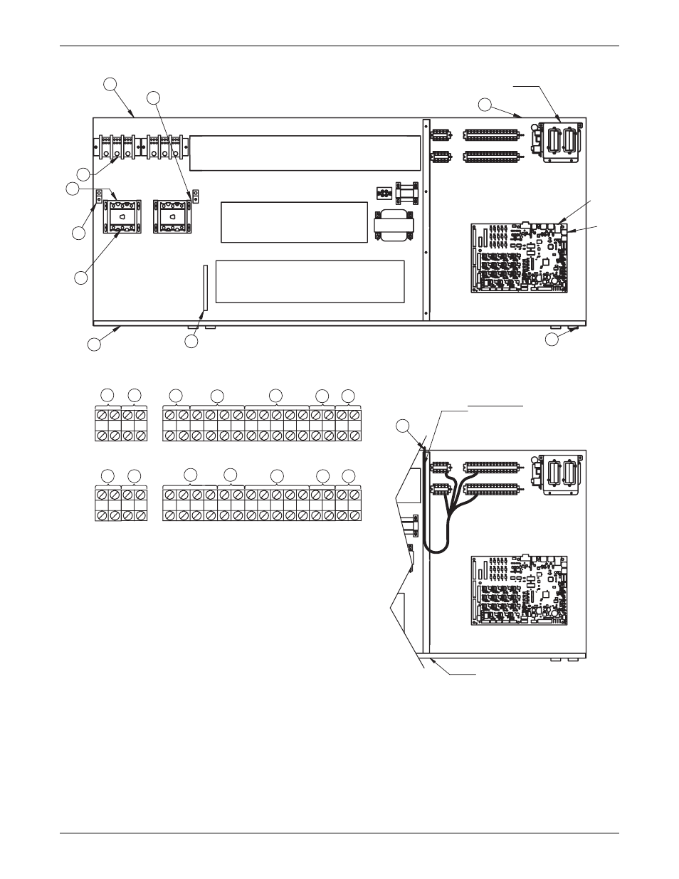
Electrical Connections
69
Figure 55 Electrical field connections
78
75 76 94 95 96 97 91
11 12 77
92 93 80 81
73
37C 38C 37B 38B
37 38 24
70 71 72
50 51 55 56
88
83
82
89
84
59
58
85
16
17
10
15
18
9
19
11
8
20
22
23
21
7
3
1
12
6
14
5
2
13
4
A
B
6
3
IntelliSlot Housing
60 Hz
OVERLOAD PROTECTORS
CONTACTORS
CONTACTORS & RELAYS
50 Hz
Note: Typical orientation of components shown. Component location varies by option and unit size.
Risk of broken or shorted low volt
wiring. Field-installed low volt wiring
must be routed with loop as shown
to allow electric box to swing.
UPFLOW
DOWNFLOW
Note: Refer to DPN000807 for descriptions of numbered callouts.
UPFLOW LOW VOLT SECTION
POINT OF HINGED LOW
VOLT ELECTRIC BOX
P64
P67
DPN000806
Rev. 3
C
D
A
B
CAUTION:
C
D
DOWNFLOW LOW VOLT SECTION
Refer to 7.1 - Electrical Field Connection Descriptions
for keys to numbered items.