Liebert Precision Cooling System DS User Manual
Page 107
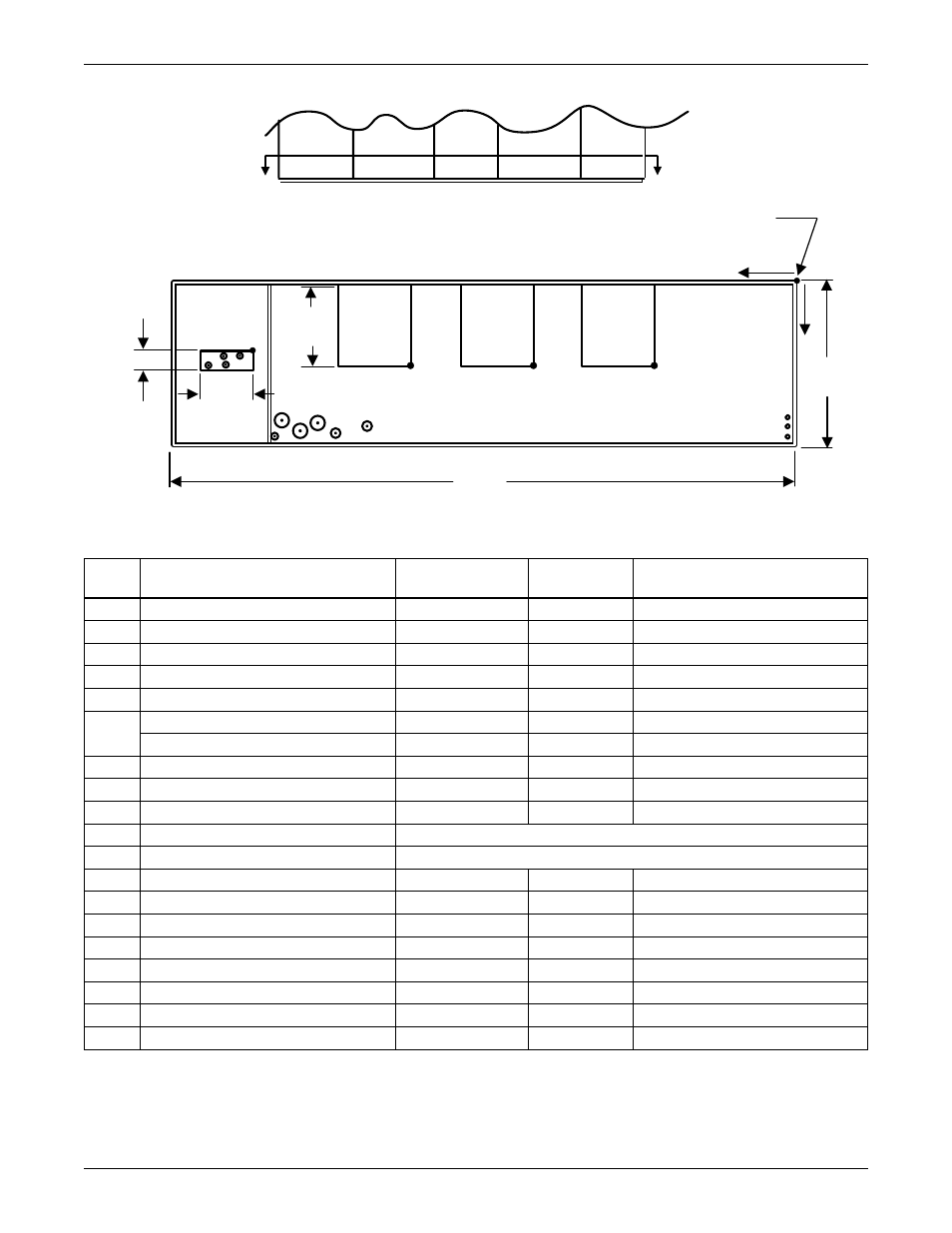
Piping Schematics
97
Figure 72 Primary connection locations—downflow, air-cooled, 105kW (30 ton), all compressor models
Point)
Description)
X
inches (mm)
Y
inches (mm)
Connection Size / Opening
inches (mm)
R
Refrigerant Access
109 (2769)
15-3/4 (400)
16-7/16 x 4 (418 x 102)
L1
Liquid Line System 1
121-3/4 (3092)
16-3/4 (425)
5/8 Cu Sweat
L2
Liquid Line System 2
118-1/8 (3000)
16-3/4 (425)
5/8 Cu Sweat
G1
Hot Gas Discharge 1
118-1/4 (3004)
14-1/4 (362)
1-1/8 Cu Sweat
G2
Hot Gas Discharge 2
115-5/8 (2937)
14-1/4 (362)
1-1/8 Cu Sweat
CD
Condensate Drain *
83-13/16 (2129)
30 (762)
3/4 FPT
W/ Optional Pump
83-13/16 (2129)
30 (762)
1/2 Cu Sweat
HUM
Humidifier Supply Line
102-3/4 (2610)
31-3/4 (806)
1/4 Cu Sweat
ECS** Econ-O-Coil Supply
101-7/8 (2588)
29 (737)
2-5/8 Cu Sweat
ECR** Econ-O-Coil Return
94-9/16 (2402)
29 (737)
2-5/8 Cu Sweat
HS
Hot Water Reheat Supply
Consult Factory
HR
Hot Water Reheat Return
Consult Factory
E1
Electrical Connection (High Volt)
98-1/8 (2492)
31-1/4 (794)
2-1/2
E2
Electrical Connection (High Volt)
91 (2311)
31-1/4 (794)
2-1/2
LV1
Electrical Connection (Low Volt)
2 (51)
28-1/4 (718)
7/8
LV2
Electrical Connection (Low Volt)
2 (51)
30-1/4 (768)
7/8
LV3
Electrical Connection (Low Volt)
2 (51)
32 (813)
7/8
B1
Blower Outlet
27-7/8 (708)
18 (457)
14-1/2 x 15-11/16 (368 x 398)
B2
Blower Outlet
52-1/16 (1322)
18 (457)
14-1/2 x 15-11/16 (368 x 398)
B3
Blower Outlet
76-1/4 (1937)
18 (457)
14-1/2 x 15-11/16 (368 x 398)
* Field-pitch condensate drain line a minimum of 1/8" (3.2 mm) per foot (305 mm). All units contain a factory installed condensate trap. Do not
trap external to the unit. Drain line may contain boiling water. Select appropriate drain system materials. The drain line must comply with all
local codes.
** Supplied on Dual-Cool systems only (4-pipe system).
16-7/16"
(418mm)
Section A-A
Front View
A
A
X
Y
O
Tolerance on all
piping dimensions
is ± 1/2" (13mm)
131"
(3327mm)
Front of Unit
Note: Drawing not to scale
DPN001014
Rev. 2
G2
L1
G1
LV3
LV2
LV1
ECS
HUM
CD
ECR
E1 E2
B1
Blower
Outlet
Blower
Outlet
Blower
Outlet
B2
B3
R
L2
4" (102mm)
15-11/16"
(398mm)
35"
(889mm)
All dimensions
from rear corner
of unit including
panels