Life Fitness G3 User Manual
Page 16
15
S
TEP
6:
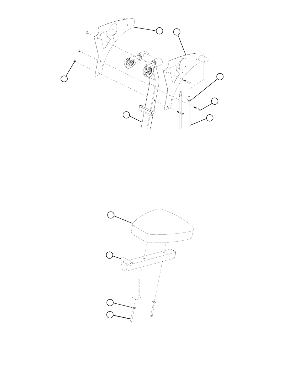
A. Swing the GUIDE RODS (18) into the guide rod bushings in the RIGHT BOOM PLATE (14) and
LEFT BOOM PLATE (15) as shown in Figure 6.
B. Loosely assemble the RIGHT BOOM PLATE (14) and LEFT BOOM PLATE (15) to the UPRIGHT
(2) using three 3/8 x 3-3/4" BOLTS (57) and three 3/8" SILVER LOCK NUTS (63). See Figure 6.
D. Slide the SHAFT COLLARS (36) to the top of the GUIDE RODS (18) and tighten the set screws
as shown in Figure 6.
S
TEP
7:
A. Securely assemble one SEAT PAD (16) to the SEAT ADJUST (7) using two 3/8 x 3" SILVER
BOLTS (67) and two 3/8" WASHERS (64). See Figure 7.
3/8 X 3-3/4”
2
63
18
14
36
57
15
F
IGURE
6
7
16
3/8 X 3”
64
67
F
IGURE
7
See also other documents in the category Life Fitness Sports and recreation:
- F3 Folding Treadmill (12 pages)
- T3 Treadmill (6 pages)
- T5 Treadmill (1 page)
- T7 Treadmill (8 pages)
- T3 Treadmill (19 pages)
- Platinum Club Series Treadmill (21 pages)
- Arctic Silver T3.5 Treadmill (9 pages)
- FZTP (17 pages)
- MTSLE (18 pages)
- Sport and Essential Consumer Treadmills (3 pages)
- CTSX30-0102-01 (8 pages)
- Cable Motion 8352100 REV. B (26 pages)
- Cable Motion 39721 (24 pages)
- Pro 2 Series PSPD (11 pages)
- 91Xi (83 pages)
- 91TW (22 pages)
- Utility Bench (8 pages)
- Hammer Strength OHDRacks (6 pages)
- 8216 (7 pages)
- GS5 (11 pages)
- TR-7500 (3 pages)
- Parabody 805 (11 pages)
- HDCR9 (13 pages)
- 18 \ 90 Series (8 pages)
- OHD-MIP (10 pages)
- Pro 2 Series PSFLY (10 pages)
- Hammer Strength OHDMR (15 pages)
- GS6 (1 page)
- UPRIGHT LIFECYCLE 95C (1 page)
- LIFECYCLE R3 (2 pages)
- GS4 (12 pages)
- FZHAD (13 pages)
- FIT 3 (1 page)
- 889 (16 pages)
- MTSRL (21 pages)
- 887 (16 pages)
- GK53-00002-0012 (2 pages)
- C3 (2 pages)
- Pro 2 Series PSSLPSE (22 pages)
- T7i (8 pages)
- Arctic Silver 93XW-0XXX-03 (17 pages)
- 874 (12 pages)
- Classic Series Cross-Trainer CLSXH (8 pages)
- Exercise Bike Inspire Console 97C Lifecycle (42 pages)
- Hammer Strength MTS (6 pages)