Installation, Installation with a chilled water system – Lochinvar 000 - 2 User Manual
Page 26
INSTALLATION
Continued
Sludge formed as the result of excessive oxygen in the system
can restrict water flow resulting in a premature boiler failure.
Any boiler damage due to excessive oxygenation is non-
warrantable.
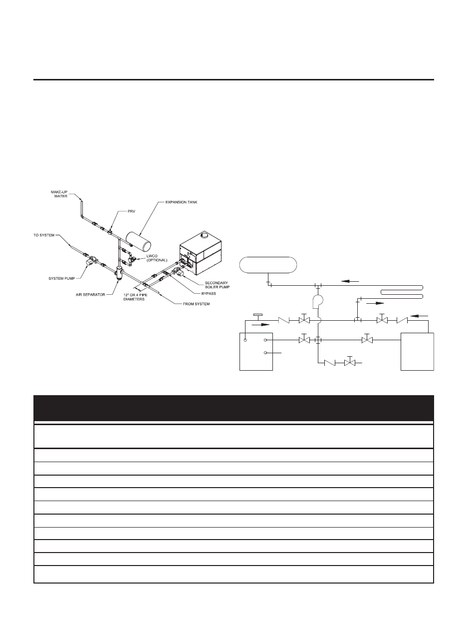
Figure 28 - Boiler with Low Temperature Bypass Piping
Installation with a Chilled Water
System
Pipe refrigeration systems in parallel. Install duct coil
downstream at cooling coil. Where the hot water heating boiler
is connected to a heating coil located in the air handling units
which may be exposed to refrigeration air circulation, the
boiler piping system must be equipped with flow control
valves or other automatic means to prevent gravity circulation
of the boiler water during the cooling cycle. The coil must be
vented at the high point and hot water from the boiler must
enter the coil at this point. Due to the fast heating capacity of
the boiler, it is not necessary to provide a ductstat to delay
circulator operation. Also, omit thermostat flow checks as the
boiler is cold when heating thermostat is satisfied. This
provides greater economy over maintaining standby heat (see
Figure 29).
Figure 29 - Installation with a Chilled Water System
Hydronic Heating Boilers and
Domestic Water Heaters
26
System Temperature Risased on Btu/hr Input
T
T
T
T
T
T
10ºF
20ºF
30ºF
40ºF
50ºF
60ºF
Input
Output
GPM FT. HD GPM FT.HD
GPM FT.HD
GPM FT.HD
GPM FT.HD
GPM FT.HD
495,000
400,950
80+
*
40
4.0
27
1.6
20
0.7
16
0.6
13
0.6
645,000
522,450
129+
*
52
5.1
35
3.0
26
1.6
21
0.8
17
0.6
745,000
603,450
149+
*
60
*
40
4.0
30
2.3
24
1.2
20
0.7
985,000
831,600
197+
*
80
5.2
53
2.4
40
1.4
32
1.0
27
0.8
1,255,000
1,058,400
251+
*
102+
*
68
4.3
51
2.5
41
1.6
34
1.1
1,435,000
1,209,000
288+
*
116+
*
78
6.0
58
3.7
47
2.2
39
1.7
1,795,000
1,512,000
360+
*
146+
*
97+
*
73
6.2
58
4.2
49
2.4
2,065,000
1,738,800
414+
*
168+
*
112+
*
84
8.7
67
6.0
56
4.5
+ These flow rates exceed recommended flow rates of boiler. If these system temperature rises are used, an external piping by-pass must be installed.
* These foot head calculations exceed the maximum allowable flow rate of the boiler. Requires Cupro-Nickel heat exchanger.
TABLE - L
System Temperature Rise Chart Based on Btu/hr Input
EXPANSION
TANK
CHILLER
BOILER
IN
OUT
SUPPLY
GAS
WATER
SUPPLY
LOW WATER
FLOW SWITCH
COOLING COIL
HEATING AND
PUMP