Installation, Connecting to water supply, Inlet and outlet connections – Lochinvar 000 - 2 User Manual
Page 20
20
INSTALLATION
Continued
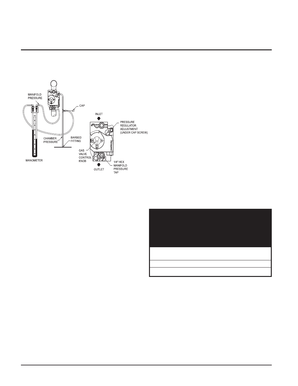
Figure 21 - Measuring Manifold Gas Pressure
2. Turn the power switch located in the lower left corner
behind the control panel access door to the “O” or “OFF”
position.
3. Remove the top front jacket access panels to access the gas
valve(s).
4. Locate the reference hose on the first gas valve which goes
from the vent fitting on the gas valve to the barbed fitting
on the deck of the unit (see Figure 21).
5. Remove the flexible cap from the barbed fitting on the
"tee" located in this line and hook one side of the
manometer, or (-) side of a magnahelic gauge, to this "tee".
Retain this cap for future use.
6. Remove the 1/8" hex plug from the manifold pressure tap
on the gas valve (see Figure 21). Retain plug for future use.
7. Install a fitting in this tap that is suitable for connection of
a hose to a manometer, or (+) side of a magnahelic gauge
(see Figure 21).
8. Turn the power switch to the “I” or “ON” position.
9. Push the reset button(s) for the ignition control(s), if
necessary.
10. Set the temperature control to call for heat (see Setting
Temperature Control, page 29).
11. Once the unit is firing, the manometer/magnahelic will
reflect the net manifold gas pressure. Compare this reading to
the respective value in TABLE-I for Natural Gas or Propane
Gas.
12. If adjustment is necessary, remove the regulator cover screw
on the gas valve. Note: If the gas valve under adjustment is
located on a manifold assembly monitored by an igniter, the
unit may shut down and recycle when the regulator cover
screw is removed. This is normal.
13. Turn the regulator adjustment screw “clockwise” to raise the
regulator gas pressure. Turn the regulator adjustment screw
“counterclockwise” to lower the regulator gas pressure.
14. Replace the regulator cover screw and make sure it is tight
for proper operation.
15. Read the value on the manometer/magnahelic and compare it
to the values in TABLE-I.
16. Repeat this adjustment procedure for each gas valve as
necessary to adjust to the proper manifold gas pressure.
17. Remove hoses, replace and tighten plugs and caps when
complete.
18. Replace top front upper jacket access panels and control
panel door in reverse order.
19. If proper ignition and burner operation is not achieved after
checking gas supply pressure, see Cleaning and
Maintenance, page 41 for Combustion Air Fan Adjustment.
Follow the procedure to adjust the combustion air fans as
necessary.
TABLE-H
CONNECTING TO WATER
SUPPLY
Inlet and Outlet Connections
For ease of service, install unions on the water inlet and water
outlet of the unit. The connection to the unit marked “Inlet” on
the header should be used for return from the system. The
connection on the header marked “Outlet” is to be connected
to the supply side of the system.
Hydronic Heating Boilers and
Domestic Water Heaters
Nat. Gas (495,000 - 745,000 Btu/hr)
1.8" w.c.
Nat. Gas (985,000 - 2,065,000 Btu/hr)
1.2" w.c.
LP Gas (495,000 - 2,065,000 Btu/hr)
4.6" w.c.
TABLE - I
NET MANIFOLD PRESSURE
Regulator Pressure Less
Front Chamber Pressure