Installation, Connecting to gas supply – Lochinvar 000 - 2 User Manual
Page 16
INSTALLATION
Continued
CONNECTING TO GAS
SUPPLY
Only supply the gas type specified on the unit's rating plate.
This unit is orificed for operation up to 2000 feet altitude. If
installing above 2000 feet elevation, consult the appliance
manufacturer.
INLET PRESSURE: Measure inlet pressure at the inlet
pressure tap located upstream of the combination gas valve(s).
See TABLE-E for maximum and minimum inlet pressures. Do
not exceed the maximum. Minimum inlet pressure is for the
purposes of input adjustment.
Input
Max.
Min.
495,000 - 745,000 Btu/hr
Nat. Gas
10.5" w.c.
4" w.c.
LP Gas
13" w.c.
8" w.c.
985,000 - 2,065,000 Btu/hr
Nat. Gas
10.5" w.c.
4.5" w.c.
LP Gas
13" w.c.
8" w.c.
MANIFOLD PRESSURE: Measure manifold pressure at the
pressure tap on the downstream side of the combination gas
valves. The gas regulator on the unit's combination gas valve
is adjustable to supply proper manifold pressure for normal
operation. See TABLE-I for net manifold pressure settings.
If you must adjust regulator pressure, follow the instructions
under Gas Manifold Pressure Adjustment, page 19. Do not
increase regulator pressure beyond the specified pressure
setting.
Gas Pressure Test
1. Disconnect the unit from the gas supply piping system
during any piping system pressure testing greater than 1/2
PSIG (3.5kPa).
2. Isolate the unit from the gas supply piping system by
closing a manual shutoff valve during any piping system
pressure testing that is equal to or less than 1/2 PSIG
(3.5kPa).
3. Test all gas connections for gas leaks before placing unit in
operation.
Gas Piping
To safely operate this unit, you must properly size the gas
supply piping. See TABLES- F, G, & H for piping and fitting
requirements. Gas pipe size may be larger than heater
connection.
The gas connection for models 495,000 to 745,000 Btu/hr is
1 1/4" NPT and on models 985,000 to 2,065,000 Btu/hr the
gas connection to these units is 2" NPT.
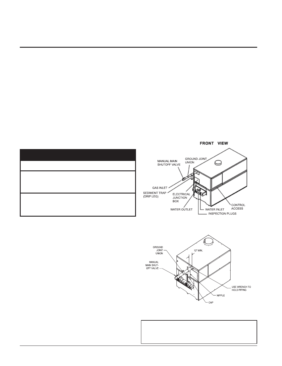
For ease of service, install a union.
Install a manual main gas shutoff valve, outside of the unit gas
connection within six feet of the unit in accordance with the
requirements of the National Fuel Gas Code, ANSI Z223.1.
You must provide a sediment trap (drip leg) in the inlet of the
gas connection to the unit.
Figure 17 - 495,000 - 745,000 Btu/hr Gas Line Connection
Example
Figure 18 - 985,000 - 2,065,000 Btu/hr Gas Line Connection
Example
IMPORTANT: Do not block access to the
electrical cover plate when installing the
sediment trap. The sediment trap must be a
minimum of 12 inches from the appliance.
Hydronic Heating Boilers and
Domestic Water Heaters
16
TABLE - E
Inlet Pressure