Hydronic piping, Installation & operation manual – Lochinvar KNIGHT WH 55 - 399 User Manual
Page 45
Installation & Operation Manual
45
BOILER
INDIRECT
DHW TANK
DOMESTIC
HOT WATER
CIRCULATOR
ANTI-SCALD
MIXING VALVE
COLD
WATER
IN
TEMPERATURE /
PRESSURE
GAUGE
AIR SEPARATOR
BALL VALVE
(TYPICAL)
UNION
(TYPICAL)
PRESSURE
RELIEF VALVE
DRAIN POINT
(TYPICAL)
MAKE UP
WATER
HOT
WATER
OUT
BOILER
CIRCULATOR
BACKFLOW
PREVENTER
PRESSURE
REDUCING VALVE
PRESSURE
GAUGE
EXPANSION
TANK
ZONE VALVES
(TYPICAL)
FLOW CHECK
VALVE
DIFFERENTIAL
PRESSURE
BYPASS VALVE
(RECOMMENDED)
SYSTEM SUPPLY
SENSOR
DRAIN
Y-STRAINER
(RECOMMENDED)
ZONE #1
ZONE #2
ZONE #3
ZONE #4
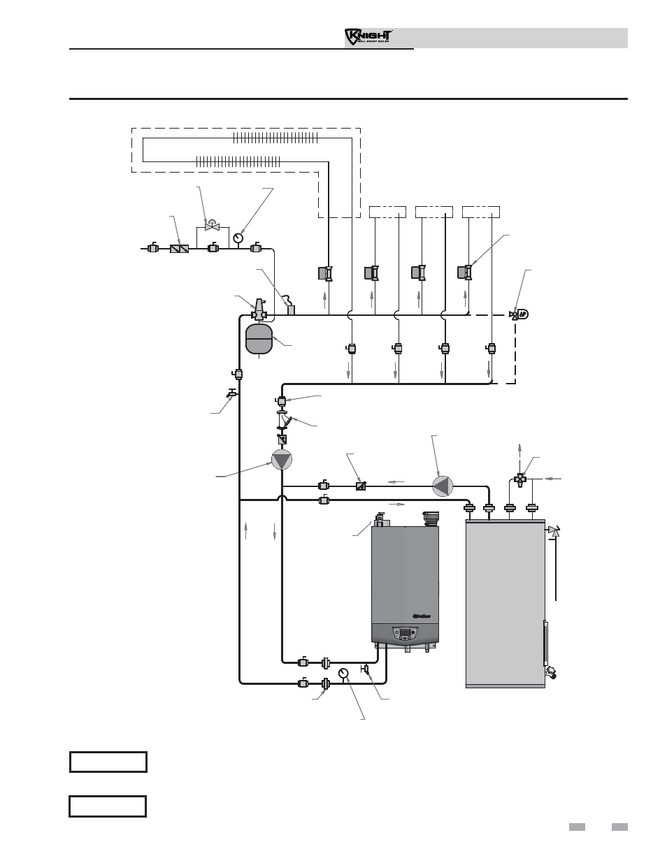
Figure 6-10 Single Boiler - Full Flow - Single Temperature - Zoned with Zone Valves - DHW Priority
6
Hydronic piping
(continued)
Please note that these illustrations are meant to show system piping concept only, the installer is responsible
for all equipment and detailing required by local codes.
NOTICE
It is the responsibility of the installer to ensure that the minimum flow requirements of the boiler are met at
all times during boiler operation. If the minimum flow requirements cannot be met at any time the boiler
must be hydraulically separated from the system.
NOTICE