Troubleshooting & repair, Flashing and rotor voltage test (continued) – Lincoln Electric COMMANDER SVM153-A User Manual
Page 86
TROUBLESHOOTING & REPAIR
F-33
F-33
COMMANDER 500
FILTER
CAPACITOR
FIELD
DIODE
RECTIFIER
BRIDGE
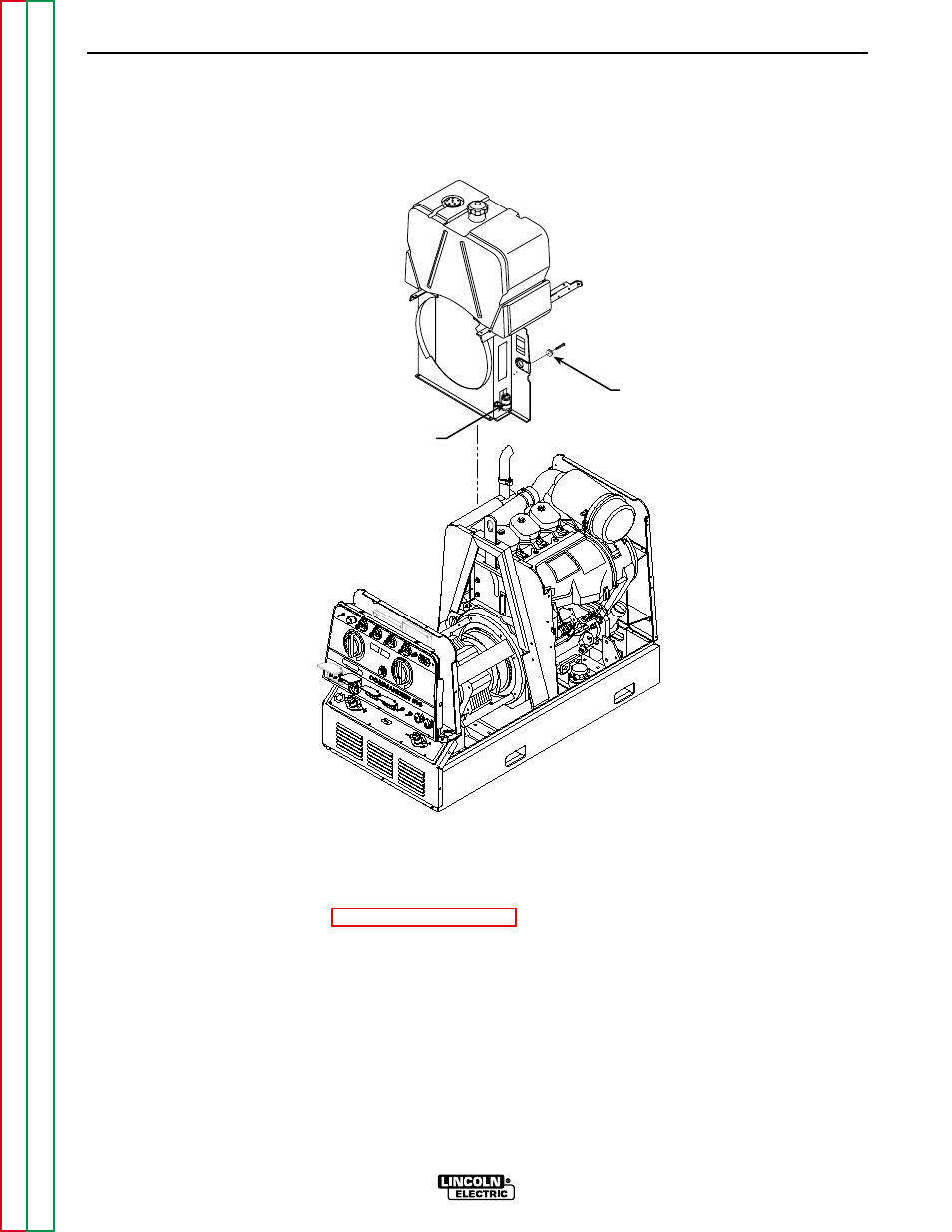
FIGURE F.12 - FIELD DIODE RECTIFIER BRIDGE AND FILTER CAPACITOR
FLASHING AND ROTOR VOLTAGE TEST(CONTINUED)
7. If the voltage reading is low or not present,
the generator field is not functioning proper-
ly. Perform the Rotor Resistance Test.
Also check the field diode rectifier bridge, fil-
ter capacitor, and associated leads and con-
nections. See Figure F.12 for location. See
the Wiring Diagram.
NOTE: The normal flashing voltage is approxi-
mately 9VDC. This is battery voltage, which is
processed through the Battery board. This volt-
age must be present during start-up to "flash"
the rotor field.
8. If the rotor voltage readings are normal, the
field circuit is functioning properly. Replace
any cable ties cut during the test. Install the
right case side.