Troubleshooting & repair, Flashing and rotor voltage test (continued) – Lincoln Electric COMMANDER SVM153-A User Manual
Page 85
TROUBLESHOOTING & REPAIR
F-32
F-32
COMMANDER 500
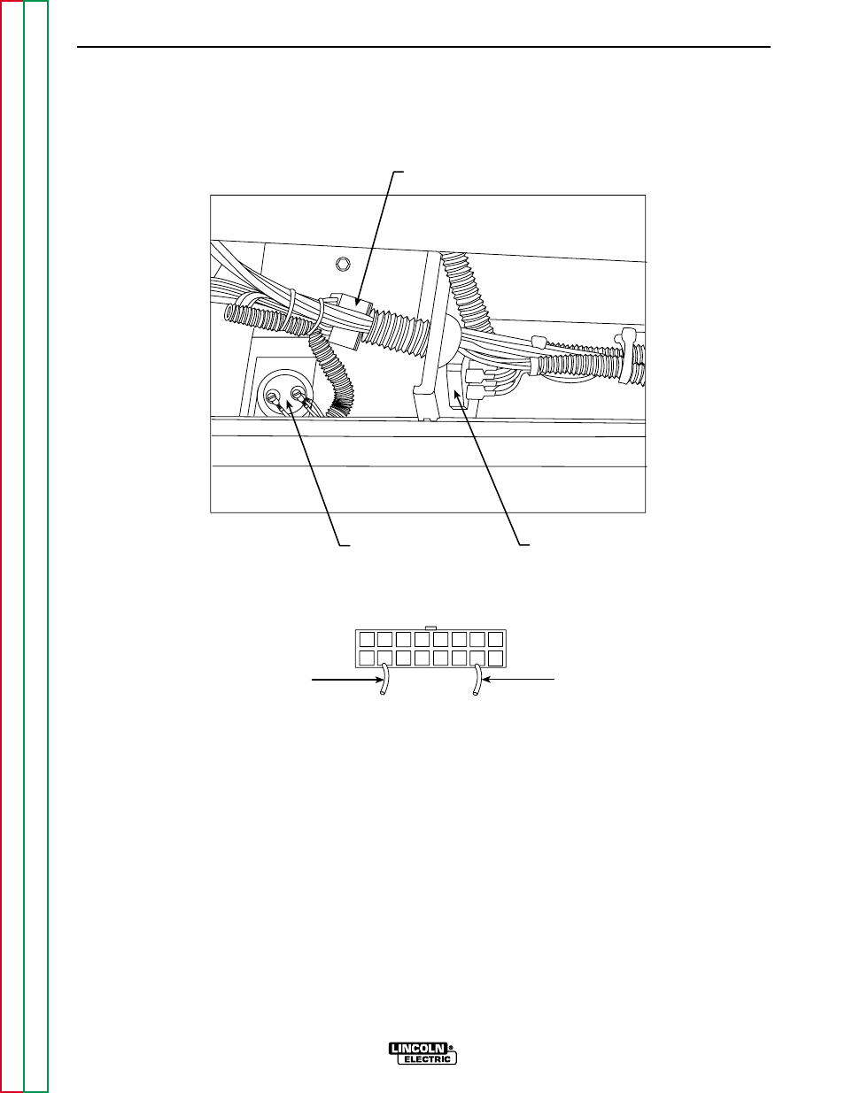
PLUG P/J52
LEAD # 200A
LEAD # 201A
PLUG P/J52
1 2 3 4 5 6 7 8
9 10 11 12 13 14 15 16
FILTER
CAPACITOR
FIELD DIODE
RECTIFIER BRIDGE
FIGURE F.11 – PLUG P/J52 LOCATION
FLASHING AND ROTOR VOLTAGE TEST(CONTINUED)
TEST PROCEDURE
1. Using the 3/8" wrench, remove the sheet
metal screws from the right front case side.
2. Carefully remove the right case side.
3. Set the volt/ohmmeter to the DC volts
position.
4. Locate Plug P/J52 and leads #200A and
#201A. See Figure F.11.
NOTE: Cut any cable ties necessary to perform
the test. DO NOT UNPLUG PLUG P/J52.
5. Connect the positive meter probe to lead
#200A and the negative meter probe to lead
#201A.
6. Start the engine and run it at high idle speed
(1900 RPM). Check the voltage reading on
the meter. It should read approximately
16 VDC.