Commander 500, Theory of operation, Engine rotor stator – Lincoln Electric COMMANDER SVM153-A User Manual
Page 50: Weld control board
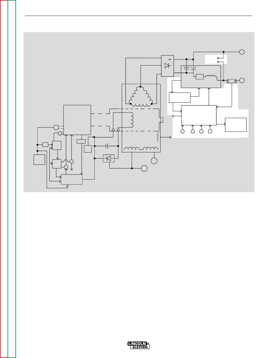
ANALOG CONTROL POWER
SUPPLY BOARD AND WELD
CONTROL BOARD
The Analog Power Supply PC board, which is powered
by 80 VDC derived from the filter capacitors on the
Power Modules, supplies various regulated DC volt-
ages to operate the Weld Control PC board circuitry. It
also supplies two regulated DC voltages to operate the
IGBT driver circuitry on the two Power Modules.
The Weld Control PC board monitors the operator con-
trols (arc control, output, and process/range selector).
It compares these commands to the current and volt-
age feedback information it receives from the shunt
and output terminal circuits. The circuitry on the Weld
Control PC board determines how the output should be
controlled to optimize welding results, and it sends the
correct PWM signals to the IGBT driver circuits. The
Weld Control PC board also commands the thermal
light and the voltmeter and ammeter (some items may
be optional).
E-4
E-4
THEORY OF OPERATION
COMMANDER 500
NOTE: Unshaded areas of Block Logic Diagram are the subject of discussion.
ENGINE
ROTOR
STATOR
AUXILIARY
WINDINGS
W
E
L
D
W
I
N
D
I
N
G
MECHANICAL
ROTATION
STARTER
ALTERNATOR
ENGINE
SENSORS
OUTPUT
PROCESS/RANGE
1
2
0
V
A
C
120VAC
RECEPTACLES (2)
240VAC
RECEPTACLE
SLIP
RINGS
ANALOG
POWER SUPPLY
BOARD
ARC
WELD
CONTROL
BOARD
CONTROL CONTROL
SELECTOR
PWM
SIGNALS (2)
VOLTMETER
AMMETER
BATTERY
S
H
U
T
D
O
W
N
I
D
L
E
R
PERIPHERAL
BOARD
BATTERY
BOARD
PULL
COIL
BOARD
SOL
SOL
TO
IDLE
HOLD
COIL
42 VAC TO 14 PIN AMPHENOL
THREE-PHASE
RECTIFIER
CHOKE
IGBT
WORK
TERMINAL
ELECTRODE
TERMINAL
+
+
SHUNT
F
E
E
D
B
A
C
K
__
__
POWER MODULES
(2)
TO WELD
CONTROL
BOARD
FOR WIRE FEEDER
COMMANDER 500
(2)
(2)
80 VDC
(2)
20 VDC
THERMAL
LIGHT
TO WELD
CONTROL
BOARD
10
VDC
10
VDC
120
VDC
1/2
BATTERY
BD
RUN/STOP
SWITCH
FIGURE E-4 – ANALOG CONTROL POWER SUPPLY BOARD AND WELD CONTROL BOARD