Table 5-44. configuration register, Table 5-45. configuration register definitions – Lantronix DSTni-EX User Manual
Page 84
76
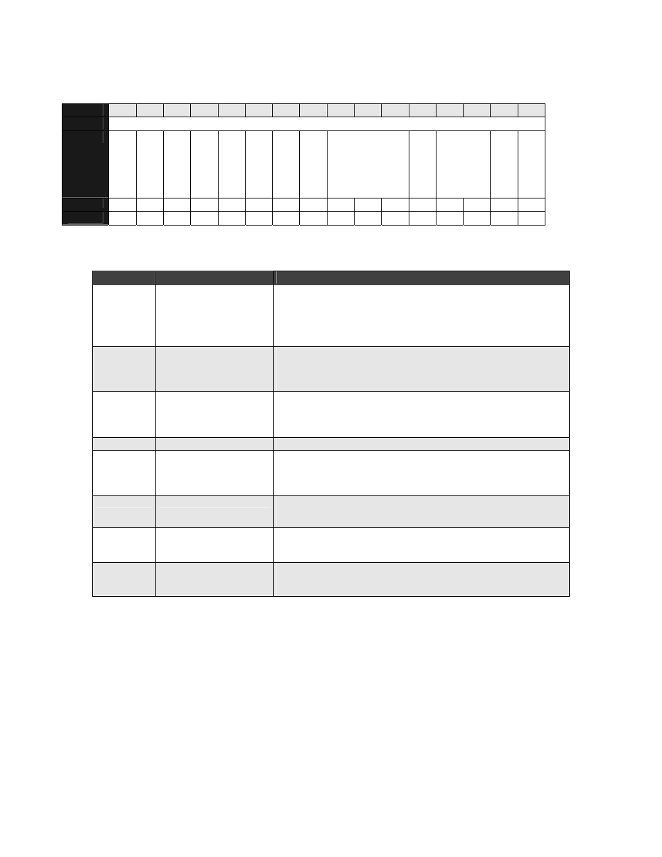
Table 5-44. Configuration Register
BIT
15
14
13
12
11
10
9
8
7
6
5
4
3
2
1
0
OFFSET
4Eh
FIELD
OV
R_MS
G
TS2_2
TS2_1
TS2_0
TS1_3
TS1_2
TS1_1
TS1_0
///
AUTO
_RES
CFG_SJW1
SAMP_MO
D
E
D
GE
_MOD
RESET
0 0 0 0 0 0 0 0 0 0 0 0 0 0 0 0
R/W
R/W R/W R/W R/W R/W R/W R/W R/W R/W R/W R/W R/W R/W R/W R/W R/W
Table 5-45. Configuration Register Definitions
Bits
Field Name
Description
15 OVR_MSG
Overwrite Last Message
1= when FIFO is full and a new message arrives it overwrites the
message in RxMsg3 buffer.
0 = under the same conditions, a new message is discarded and
no rx_msg flag is set (default).
14:12
TS[2_2:2_0]
Cfg_tseg2
Length -1 of the second time segment. Cfg_tseg2=0 is not allowed;
cfg_tseg2=1 is only allowed in direct sampling mode. See Figure
5-4.
11:8 TS[1_3:1_0]
Cfg_tseg1
Length - 1 of the first time segment (bit timing). It includes the
propagation time segment. Cfg_tseg1=0 and cfg_tseg1=1 are not
allowed. See Figure 5-4..
7:5
///
Reserved
4 AUTO_RES Auto Restart
1 = after bus off, the CAN is restarting automatically after 128
groups of 11 recessive bits.
0 = after bus off, the CAN must be started manually (default).
3:2
CFG_SJW1
Cfg_sjw
Synchronization jump width - 1.
sjwtse
g1
≤ and sjwtseg2 ≤
1 SAMP_MOD Sampling Mode
1 = three sampling points with majority decision are used.
0 = one sampling point is used in the receiver path.
0
EDGE_MOD
Edge Mode
1 = both edges are used.
0 = edge from ‘ R’ to ‘ D’ is used for synchronization (default).