Can configuration registers, Table 5-42. bit rate divisor register, Table 5-43. bit rate divisor register definitions – Lantronix DSTni-EX User Manual
Page 83: Figure 5-3. can operating mode
75
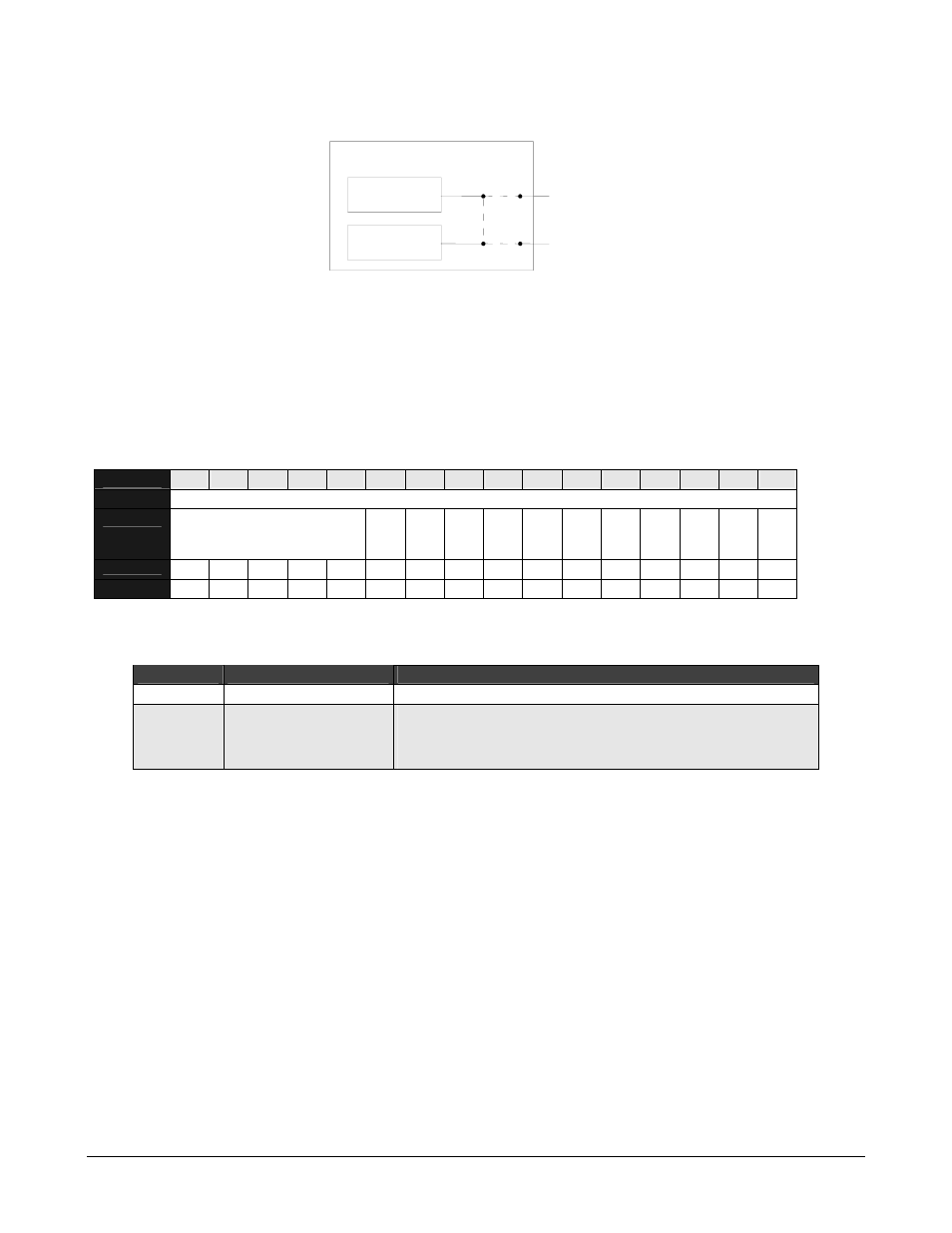
Figure 5-3. CAN Operating Mode
CAN Module 1
CAN Module 2
a
c
b
d
CAN Port 1
CAN Port 2
DSTni
Note:
The Loopback Mode register in CAN module 2 is not functional. For proper operation in
loopback mode, the configuration of both CAN modules must be the same.
CAN Configuration Registers
The following registers set bit rate and other configuration parameters.
Table 5-42. Bit Rate Divisor Register
BIT
15
14
13
12
11
10
9
8
7
6
5
4
3
2
1
0
OFFSET
4Ch
FIELD
///
BR10
BR09
BR08
BR07
BR06
BR05
BR04
BR03
BR02
BR01
BR00
RESET
0 0 0 0 0 0 0 0 0 0 0 0 0 0 0 0
R/W
R/W R/W R/W R/W R/W R/W R/W R/W R/W R/W R/W R/W R/W R/W R/W R/W
Table 5-43. Bit Rate Divisor Register Definitions
Bits
Field Name
Description
15:11 ///
Reserved
10:0
BR[10:0]
Configuration Bit Rate
Prescaler for generating the time quantum:
00000000000 = maximum speed (1 TQ = 1 clock cycle)
00000000001 = 1 TQ = 2 clock cycles