Spi controller register summary, Table 2-1. spi controller register summary – Lantronix DSTni-EX User Manual
Page 13
5
When operating as a slave, the SPI clock signal (SCLK) must be slower than 1/8th of the CPU
clock (1/16th is recommended).
Note:
The SPI is fully synchronous to the CLK signal. As a result, SCLK is sampled and then
operated on. This results in a delay of 3 to 4 clocks, which may violate the SPI specification if
SCLK is faster than 1/8th of the CPU clock. In master mode, the SPI operates exactly on the
proper edges, since the SPI controller is generating SCLK.
The SPI controller uses a 16-bit counter that is continually reloaded from DVD_CNTR_HI and
DVD_CNTR_LO. The counter divides the CPU clock by this divider and uses the result to
generate SCLK.
The SPI interface includes the internal interrupt connection, SPI interrupt.
In SPI master mode, an SPI interrupt occurs when the Transmit Holding register is
empty.
In SPI slave mode, an SPI interrupt occurs when the SLVSEL pin transitions from active
to inactive.
A familiar Interrupt Control register is provided for the SPI interrupt. The interrupt has a two
CPU clock delay from SLVSEL in slave mode because of synchronization registers.
SPI Controller Register Summary
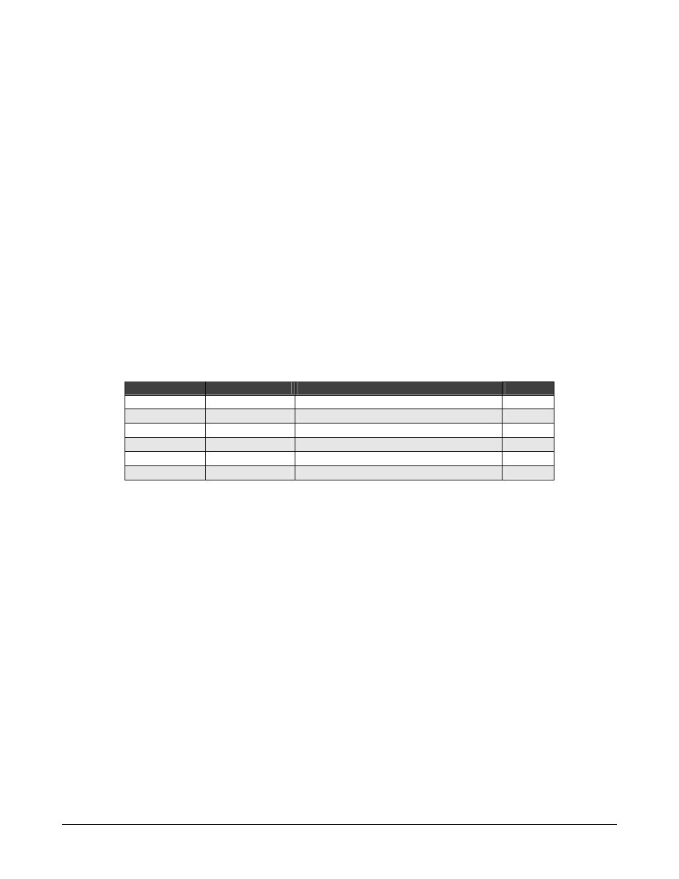
Table 2-1. SPI Controller Register Summary
Hex Address Mnemonic
Register Description
Page
B800 SPI_DATA Data
register
B802
CTL
Control register
B804 SPI_STAT Status
register
B806
SPI_SSEL
Slave Select Bit Count register
B808
DVD_CNTR_LO
DVD Counter Low Byte register
B80A
DVD_CNTR_HI
DVD Counter High Byte register