Dvd_cntr_lo register, Dvd_cntr_hi, Table 2-11. dvd_cntr_lo register – Lantronix DSTni-EX User Manual
Page 18: Table 2-12. dvd_cntr_lo register definitions, Table 2-13. dvd_cntr_hi register, Table 2-14. dvd_cntr_hi register definitions
10
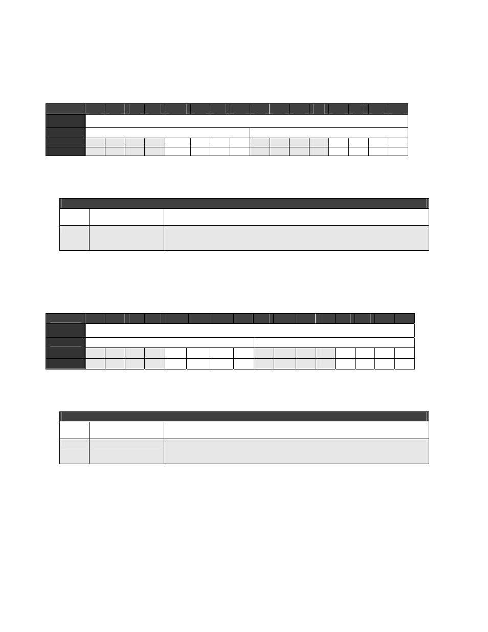
DVD_CNTR_LO Register
DVD_CNTR_LO is the DVD Counter Low Byte register.
Table 2-11. DVD_CNTR_LO Register
BIT
15
14
13
12
11
10
9
8
7
6
5
4
3
2
1
0
OFFSET
B808
FIELD
/// DVDCNT[7:0]
RESET
0
0
0
0
0 0 0 0 0
0
0
0
0 0 0 0
RW
RW
RW
RW
RW
RW RW RW RW RW
RW
RW
RW
RW RW RW RW
Table 2-12. DVD_CNTR_LO Register Definitions
Bits
Field Name
Description
15:8 ///
Reserved
Always returns zero.
7:0
DVDCNT[7:0]
Divisor Select
Selects the SPI clock rate during master mode. DVD_CNTR_HI and this byte
generate a 16-bit divisor that generates the SPI clock.
DVD_CNTR_HI
DVD_CNTR_HI is the DVD Counter High Byte register.
Table 2-13. DVD_CNTR_HI Register
BIT
15
14
13
12
11
10
9
8
7
6
5
4
3
2
1
0
OFFSET
B80A
FIELD
/// DVDCNT[15:8]
RESET
0
0
0
0
0 0 0 0 0
0
0
0
0 0 0 0
RW
RW
RW
RW
RW
RW RW RW RW RW
RW
RW
RW
RW RW RW RW
Table 2-14. DVD_CNTR_HI Register Definitions
Bits
Field Name
Description
15:8 ///
Reserved
Always returns zero.
7:0
DVDCNT[15:8]
Divisor Select
Selects the SPI clock rate during master mode. DVD_CNTR_LO and this byte
generate a 16-bit divisor that generates the SPI clock.