Konica Minolta CF5001 User Manual
Page 127
OTHER CONTROLS
CF5001 Ver.1.0 Sep. 2003
2-74
II UNIT EXPLANA
TION
D.
C (BK)
This counts up in conjunction with the paper exit counter.
E.
C (K)
This counts up in conjunction with the paper exit counter.
F.
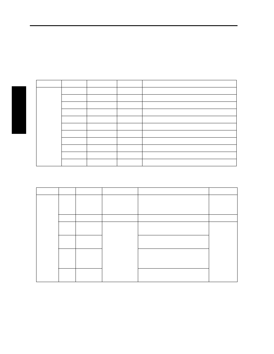
Signals in serial connection
G. Signals for status indicator lights
Connector
Pin No.
Signal name
In/Out
Description
37
1
OP_SOUT
Out
Open collector output (LS07)
2
OP_DTR
Out
Open collector output (LS07)
3
OP_CTS
In
5 V Pull up
4
OP_SIN
In
5 V Pull up
5
OP_DSR
In
5 V Pull up
6
OP_RTS
Out
Open collector output (LS07)
7
SGND
—
Signal ground
8
COPV_ENB
In
5 V Pull up
9
24 VDC
—
Power supplied to the vendor
10
PGND
—
Power ground
11
5 VDC
—
Power supplied to the vendor
Connector Pin No. Signal name
Description
Output timing
Type of signal
391
1A
DC24V
Power source of
status indicator
light
At all times
24 V,
500 mA
9B
PGND
Power ground
—
—
2A
PAT1
Light on signal
L signal outputted when print is
available
Open collec-
tor
5 V, 200 mA
3A
PAT2
L signal outputted while scanner or
printer in operation
4A
PAT3
L signal outputted when stopped
abnormally due to jamming, abnor-
mal code, no paper or no toner
5A
PAT4
L signal outputted when a toner
supply warning is displayed