Rear panel – KORG SP-500 User Manual
Page 11
11
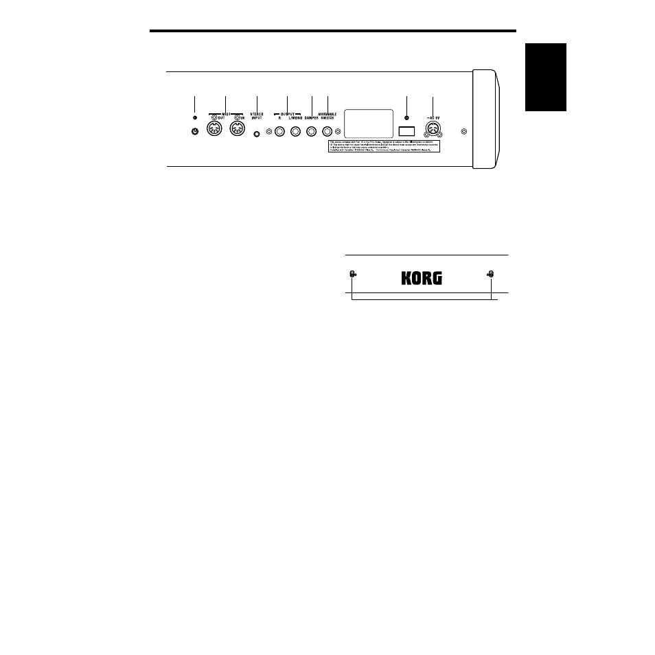
Rear panel
1. AC 9V connector
Connect the included AC/AC power supply
here. (☞p.14)
2. [POWER] switch
This switch turns the power on or off. Each
time you press it, the power will be switched on
or off. (☞p.14)
3. ASSIGNABLE SWITCH jack
The included pedal or a separately sold DS-1H
damper pedal can be connected here. (☞p.13,
33, 66)
4. DAMPER (pedal) jack
The included pedal or a separately sold DS-1H
damper pedal can be connected here. (☞p.13,
33, 66)
5. OUTPUT jacks
These jacks can be connected to the input jacks
of an audio devise to output the sound, or to a
tape recorder to record your performance. Use
the [MASTER VOLUME] slider of the SP-500 to
adjust the volume.
When making connections in stereo, use the L/
MONO jack and the R jack. When making con-
nections in mono, use only the L/MONO jack.
Use cables with 1/4 inch monaural phone
plugs.
6. INPUT jack
The output jack of a CD player or other audio
device can be connected to this jack, so that its
sound can be heard through the SP-500’s head-
phones. Use the controls of the connected audio
device to adjust the volume.
Use a stereo mini-plug (1/8 inch) cable.
7. [MIDI] connectors
These connectors can be connected to other
MIDI devices such as a synthesizer, sequencer,
or rhythm machine, so that data can be
exchanged with these devices.
☞p.69 “1. Connecting MIDI equipment”
8. Contrast
This adjusts the contrast of the screen. (☞p.15)
9. Holes for attaching the music stand (☞p.14)
Attach the included music stand using these
two holes.
5
6
7
8
4
2
3
1
9