Rs-232 cable, Additional oem interface signals – Silex technology WLAN MODULE SX-550 User Manual
Page 23
SX-550 Evaluation Daughtercard
Hardware Configuration
silex Page
17
Part Number 40183-101
GPIO LED
GPIO_10 D3
green
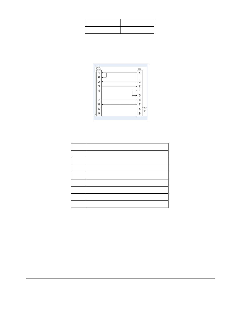
RS-232 Cable
The supplied DB-9 female-to-female null modem cable is wired as shown below.
Figure 9 RS-232 Cable Pinouts
Table 10 RS-232 Cable Pinout Description
Pin Description
1
DCD (Data Carrier Detect) Input
6
DSR (Data Set Ready) Input
2
RxD (Receive Data) Input
3
TxD (Transmit Data) Output
4
DTR (Data Terminal Ready) Output
7
RTS (Request To Send) Output
8
CTS (Clear To Send) Input
5 Ground
Additional OEM Interface Signals
The output LED signals ORLED-, GRLED- and YELED- represent the state of the LEDs on the module.
Logic 0 indicates the LED is on, and Logic 1 indicates the LED is off. Buffers are recommended if LEDs
are to be driven on the end-user side.
The SWITCH signal is connected to a momentary pushbutton switch on the evaluation daughtercard and
is in the normally open position. Depressing the switch causes a short to ground. A 4.7 K-ohm pull-up
resistor to +3.3 VDC is connected. The module’s processor monitors this signal. The end-user can drive
or use open-collector to this signal to either logic level or can monitor this signal as an input.