Rear panel, 6overview – Sony XC-HR300 User Manual
Page 6
6
Overview
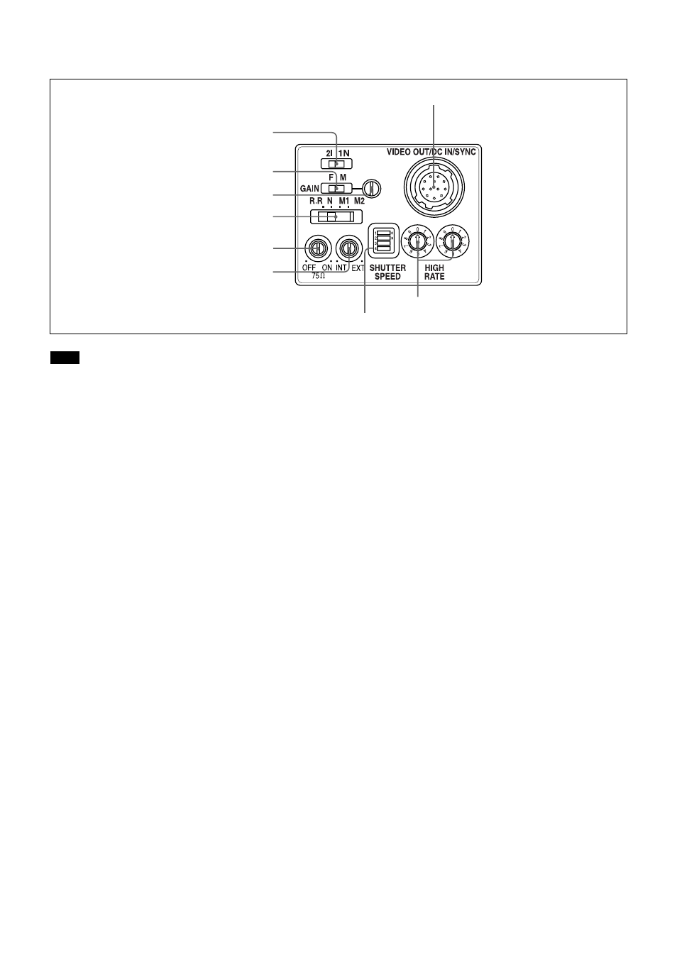
Rear Panel
Note
When you do switch settings, make sure the unit is off.
1
Read mode selector
This switch selects either the 2I mode (interlace) or the
1N mode (non-interlace).
2
GAIN switch
This switch selects fixed gain (F) or manual gain
control (M). (Factory setting: F)
3
Manual gain control
When the GAIN switch 2 is set to M (Manual), adjust
the gain using this control.
4
Restart reset/External trigger shutter mode
switch
The factory setting is N (Normal).
5
75
Ω termination switch
Turn this to OFF when not terminated. (Factory
setting: ON)
6
HD/VD signal input/output switch
Set the switch to INT to output HD/VD signals from
the camera module.
Set the switch to EXT to input HD/VD signals from an
external unit. (Factory setting: EXT)
1
Read mode selector
2
GAIN switch
3
Manual gain control
4
Restart reset/External trigger shutter
mode switch
5
75
Ω termination switch
6
HD/VD signal input/output switch
7
SHUTTER SPEED setting DIP switch
8
HIGH RATE (Partial scanning) controls
9
VIDEO OUT/DC IN/SYNC (video output/DC power
input/sync signal I/O) connector (12-pin)
7
SHUTTER SPEED setting DIP switch
Set an appropriate shutter speed when you have set the
restart reset/external trigger shutter mode switch 4 to
external trigger shutter mode M1 or M2. (Factory
setting: shutter OFF)
8
HIGH RATE (Partial scanning) controls
These controls operate when you have set the restart
reset/external trigger shutter mode switch 4 to R.R,
M1 or M2.
Increasing the number by one with the ten’s digit
control (left side) decreases the effective video output
lines by 50 ~ 60 lines*. Increasing the number by one
with the first’s digit control (right side) decreases the
effective video output lines by 5 ~ 6 lines*.
The partial scanning operation is turned off when both
controls are set to 0.
* For details of the relation between effective pixels and
BLKG, see “Example of Usage of the Partial Scanning
Mode (Restart/Reset)”, page 12 and 13, or “Example of
Usage of the Partial Scanning Mode (Trigger shutter) “,
page 15 and 16.
9
VIDEO OUT/DC IN/SYNC (video output/DC
power input/sync signal I/O) connector (12-pin)
Connect a CCXC-12P05N camera cable to this
connector for the +12V DC power supply and the
video signal output from the camera module. When a
sync signal generator is connected to this connector,
the camera module is synchronized with the external
sync signals (HD/VD signals).