Power button, Reset button – SUPER MICRO Computer X7SBL-LN1/LN2 User Manual
Page 32
2-14
X7SBL-LN1/LN2 User’s Manual
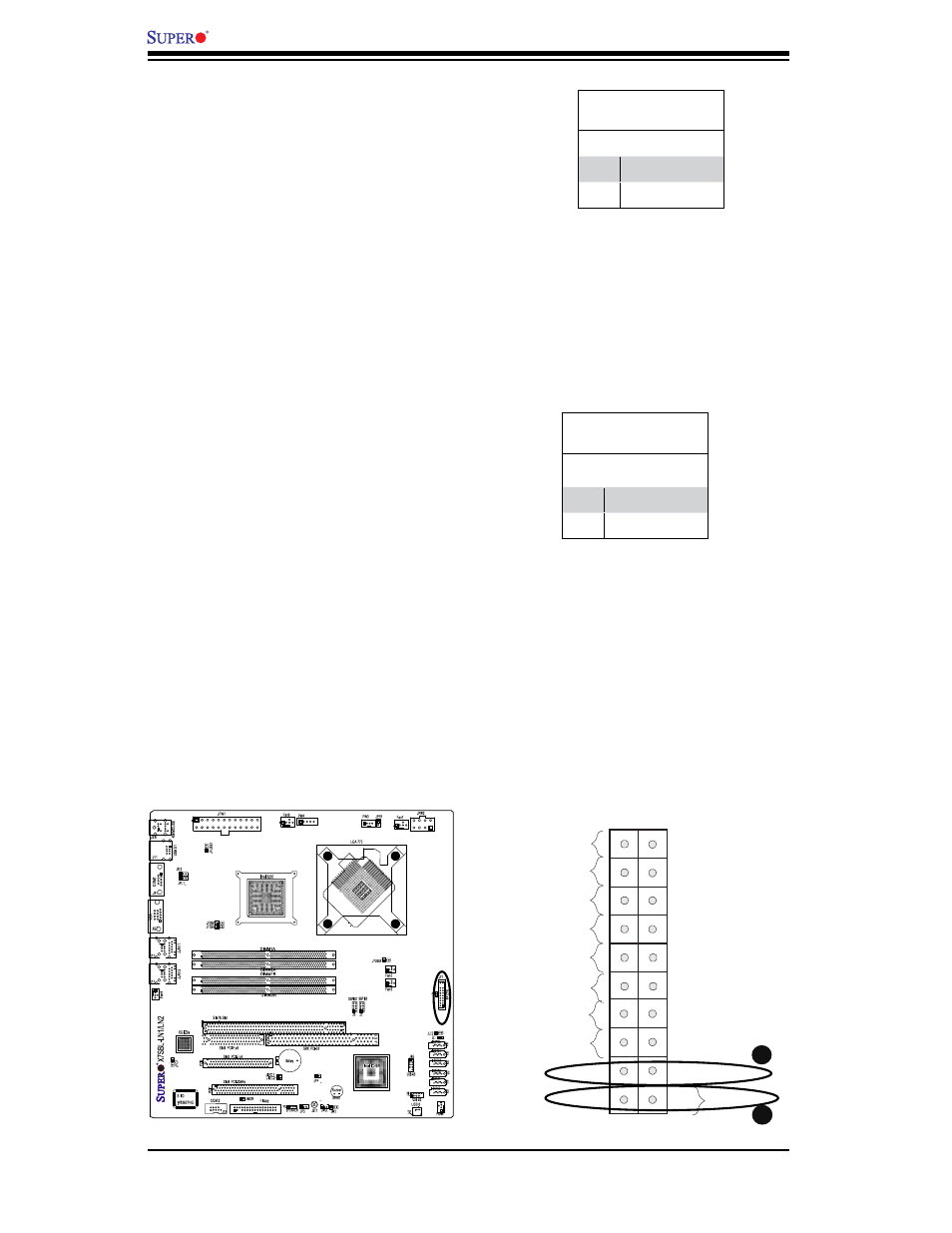
Power Button
The Power Button connection is located
on pins 1 and 2 of JF1. Momentarily con-
tacting both pins will power on/off the sys-
tem. This button can also be confi gured
to function as a suspend button (with a
setting in the BIOS - see Chapter 4). To
turn off the power when set to suspend
mode, press the button for at least 4
seconds. Refer to the table on the right
for pin defi nitions.
Power Button
Pin Defi nitions (JF1)
Pin# Defi nition
1
Signal
2
+3V Standby
A. Reset Button
B. PWR Button
Reset Button
The Reset Button connection is located
on pins 3 and 4 of JF1. Attach it to the
hardware reset switch on the computer
case. Refer to the table on the right for
pin defi nitions.
Reset Button
Pin Defi nitions (JF1)
Pin# Defi nition
3
Reset
4
Ground
Header Pins
FP Power Button
OH/Fan Fail/
PWR Fail/UID LED
1
NIC1 LED
FP Reset Button
2
HDD LED
Power LED
Reset
PWR
Vcc
UID Switch/Vcc
Vcc
Blue_LED_Cathode
(UID)/Vcc
Ground
Ground
19
20
Vcc
X
Ground
NMI
X
Vcc
PWR Fail LED
NIC2 LED
B
A