Front control panel, X7sbl-ln1/ln2 user’s manual, A. jf1 – SUPER MICRO Computer X7SBL-LN1/LN2 User Manual
Page 28
2-10
X7SBL-LN1/LN2 User’s Manual
FP Power Button
OH/Fan Fail/
PWR Fail/UID LED
1
NIC1 LED
FP Reset Button
2
HDD LED
Power LED
Reset
PWR
Vcc
UID Switch/Vcc
Vcc
Blue_LED_Cathode
(UID)/Vcc
Ground
Ground
19
20
Vcc
X
Ground
NMI
X
Vcc
PWR Fail LED
NIC2 LED
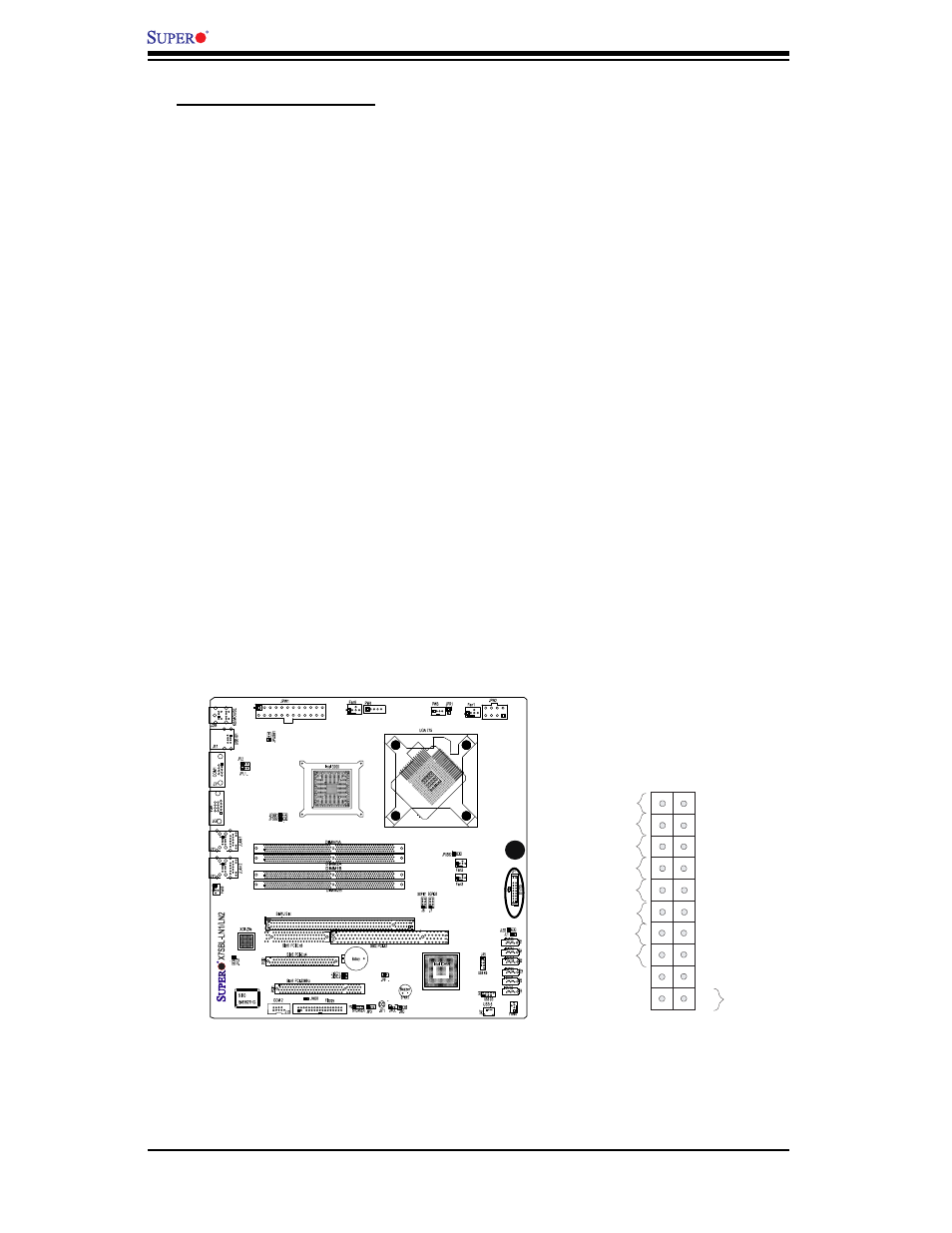
2. Front Control Panel
JF1 contains header pins for various buttons and indicators that are normally lo-
cated on a control panel at the front of the chassis. See the image below for the
descriptions of the various control panel buttons and LED indicators. Refer to the
following section for descriptions and pin defi nitions.
Header Pins
A. JF1
A