Discharge pipe and pressure tank connections 8, Pre-charge tank connection (figure 12), Standard tank connection (figure 13) – Simer Pumps 3307P User Manual
Page 8
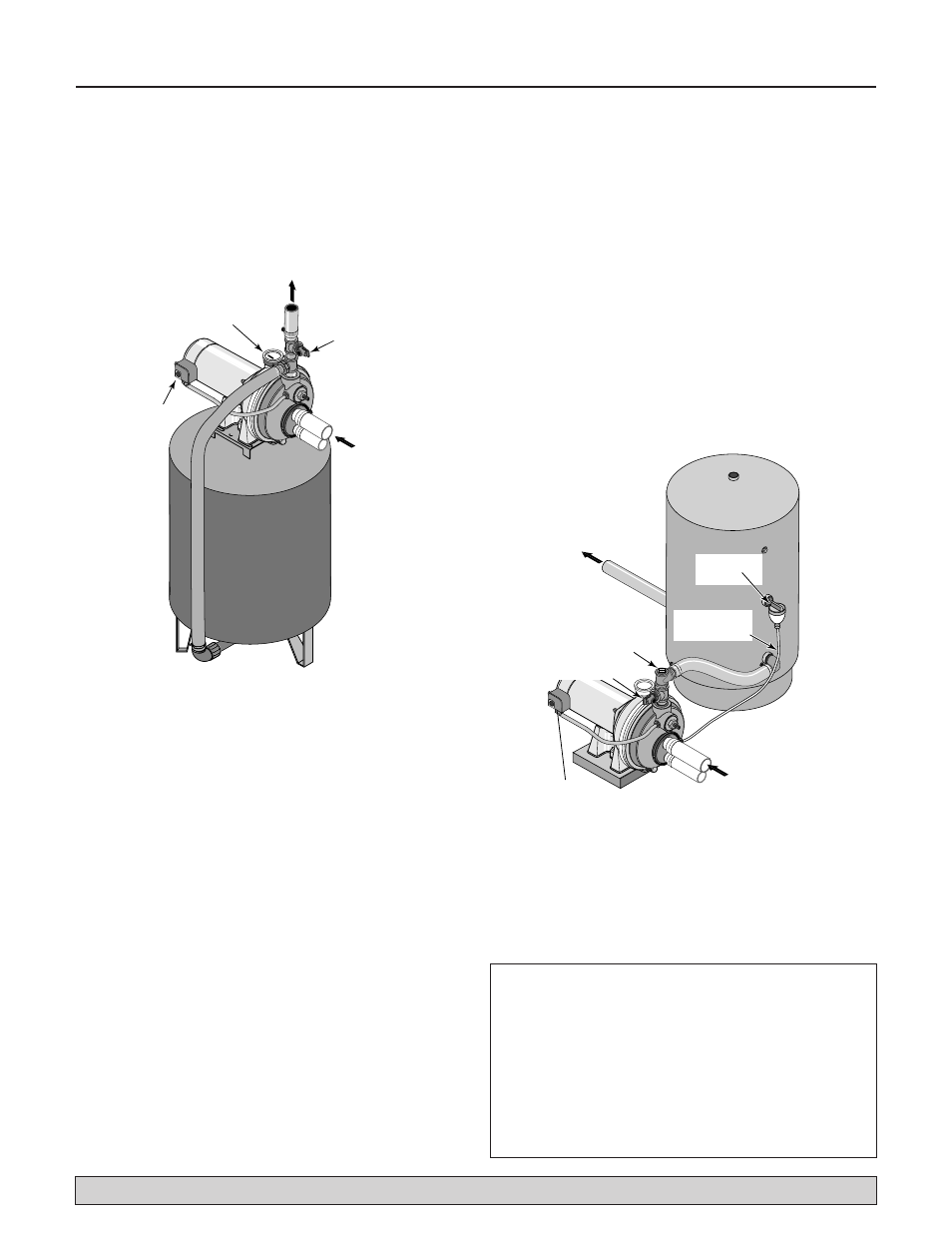
Discharge Pipe and Pressure Tank Connections
8
PRE-CHARGE TANK CONNECTION
(Figure 12)
1. Install a close nipple and a tee in the pump discharge
port (see Figure 12). The pipe size must be at least as
large as the discharge port. Run a pipe or reinforced
hose from one arm of the tee to the port on the pre-
charged tank.
2. Install a second close nipple and tee with a relief
valve in the tee.
3. Connect the other end of the second discharge tee to
your plumbing system.
4. Check the pre-charge of air in the tank with an ordinary
tire gauge. The pre-charge should be 2 PSI less than the
cut-in setting of the pump’s pressure switch. The pre-
charge is measured
when there is no water pressure in
the tank. Your new pump has a 30/50 PSI switch, so
adjust the tank pre-charge pressure to 28 PSI.
You have just completed the tank connection for your
jet pump. Please go to Pages 9 and 10 for electrical
hookup.
STANDARD TANK CONNECTION
(Figure 13)
1. Install a close nipple and a tee in the pump discharge
port. Mount a relief valve in one arm of the tee.
2. Install a second close nipple and tee in the open arm
of the first tee. Put a priming plug in one arm of the
second tee.
3. Run a pipe from the open arm of the second tee to
the inlet port of your tank. The pipe size must be at
least as large as the pump
discharge port.
4. Remove the 1/8" NPT pipe plug from the pump Air
Volume Control (AVC) port (see Figure 13). Run tub-
ing from the pump’s AVC port to the port on the AVC
mounted on the tank. See instructions provided with
tank and AVC for details.
You have just completed the tank connection for your
jet pump. Please go to Pages 9 and 10 for electrical
hookup.
P
268 0395
To Household
Water System
Pressure Gauge
and Priming
Plug
Pressure
Switch
From
Well
Relief
Valve
For parts or assistance, call Simer Customer Service at
1-800-468-7867 / 1-800-546-7867
To Household
Water System
Pressure
Switch
From
Well
Air Volume
Control
Air Volume
Control Tube
P
Priming Tee
and Plug
276 0395
Relief Valve
Figure 12: Pre-charged Tank Connections
Figure 13: Standard Tank Connections
Sealing Pipe Joints
Use only Teflon tape or Teflon based joint com-
pounds for making all threaded connections to the
pump itself. Do not use pipe joint compounds on
plastic pumps: they can react with the plastic in
pump components. Make sure that all pipe joints in
the suction pipe are air tight as well as water tight.
If
the suction pipe can suck air, the pump will not be
able to pull water from the well.