J Page 33
-31-
Df[\cN(/)0D]^%J`eZ\0&((
J
M
@:<
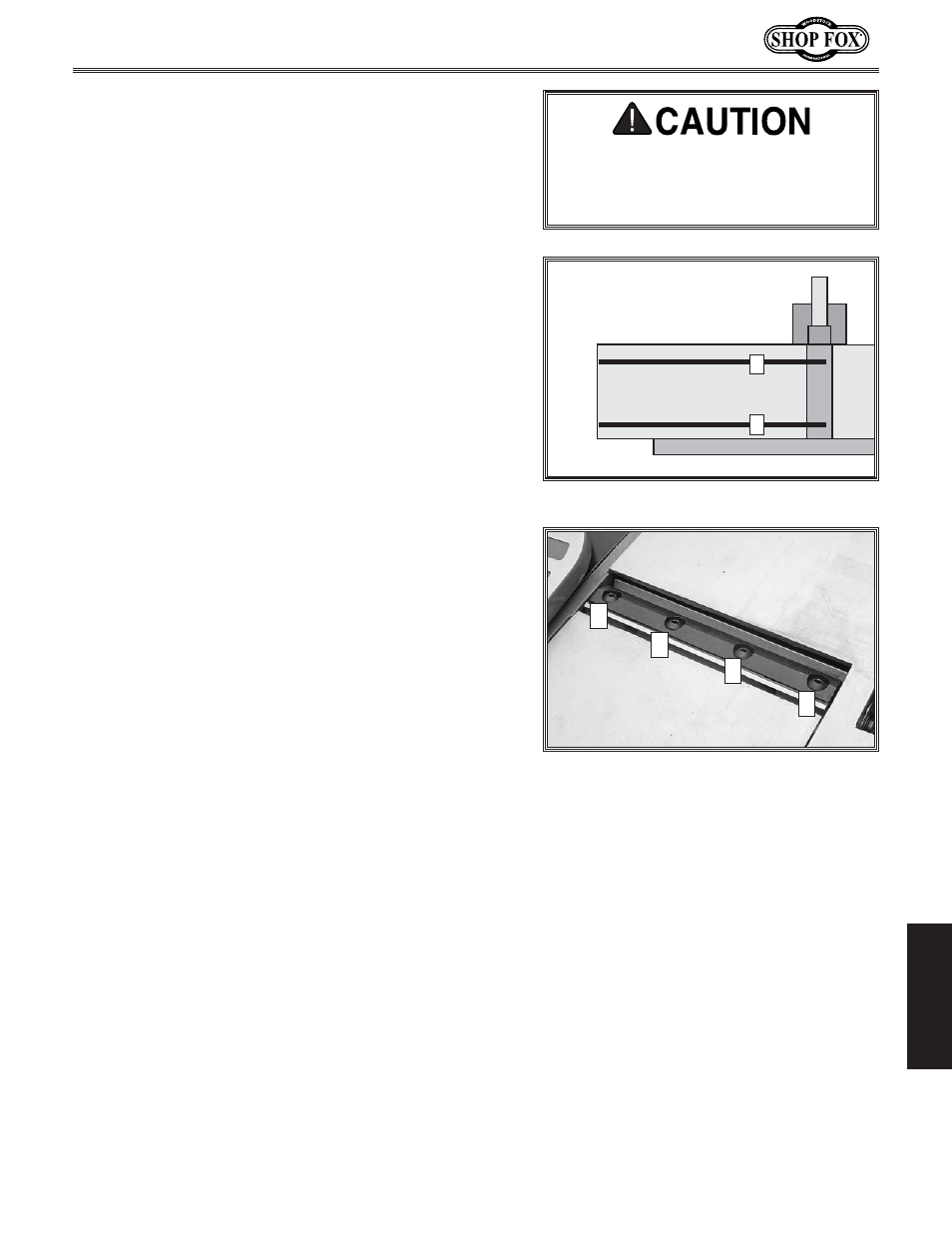
-% Move the straightedge to position A, as shown in
Figure 39. Turn the jack screw nearest the fence
counterclockwise until the end of the knife touches
the straightedge.
.% Move the straightedge to position B, as shown in
Figure 39. Turn the jack screw nearest the guard
counterclockwise until the end of the knife touches
the straightedge.
/% Slightly tighten the clamp screws, according to the
proper tightening sequence, as shown in Figure 40.
Repeat Steps 6–7 for the other cutterhead knife.
Efk\: Jc`^_kcpk`^_k\e`e^k_\ZcXdgjZi\njdX`ekX`ej
k_\be`]\gfj`k`fen_`c\g\i]fid`e^k_\jXd\jk\g
fek_\fk_\ibe`]\%K_\pn`ccY\]`eXck`^_k\e\[`eX
cXk\ijk\g%
/% Without disturbing the knife clamp, rotate the
cutterhead slightly to check the knife height.
— If the knife moves the straightedge slightly (
1
/
8
")
forward and back on the table, the knife height is
set correctly.
— If the knife does not move the straightedge
slightly (
1
/
8
") forward and back on the table,
continue to make fine adjustments with the jack
screws until the knife is set correctly.
('% When the knife heights are set correctly, final
tighten each of the knives' clamp screws according
to the proper tightening sequence (see Figure 40).
11. Return the cutterhead guard to the operating
position and ensure it is working properly.
12. Re-align the fence and tables as needed.
13. Perform a test cut on suitable piece of scrap
material.
Black Lines Represent
Straightedge Positions
From Overhead View
Figure 39
% Straightedge positions A and B.
B
A
=`^li\40% Knife clamp screw tightening
sequence.
1
2
4
3
:lkk\i_\X[ be`m\j Xi\ j_Xig Xe[
cXZ\iXk`fe `eali`\j dXp fZZli% Lj\
ZXlk`fe n_\e _Xe[c`e^ k_\ Zlkk\i_\X[
be`m\j%