Control modules, Application of control modules, Means of linking – Siemens FC700A User Manual
Page 40: Details see chapter 17, 17 control modules, 1 application of control modules, 2 means of linking
Control modules
40
Siemens Building Technologies
007836_a_en_--.doc
Fire & Security Products
03.2004
17 Control
modules
17.1 Application of control modules
Activation of fire control installations (shutting-down ventilation, closing fire
dampers etc.)
Activation and monitoring of alarm device
Activation and monitoring of remote transmission equipment
Activation of Mimic Display panels
17.1.1 Overview of the available modules with control outputs
Modules Monitored
con-
trol lines
For alarm devices
Driver outputs
Programmable
Contact outputs
(Volt free)
Programmable
Remote transmis-
sion interface
To remote transmis-
sion equipment
E3G070
2 7
1) 2)
✔
E3L020 16
1)
E3G050
8
E3G060
6
5)
K3R072
48
3)
K3G060
24 NO contact
4)
K3I110
16 NO contact
5)6)
1
Can also be used as control inputs (e.g. 'acknowledgement')
2
These inputs/outputs also serve for the activation of the remote transmission
equipment
3
For activation of Mimic Display panel, connected to the operating terminal
B3Q700 or K3I050 (no I-Bus module) -> Details see chapter 17.7
4
Applicable only with K3R072 -> Details see chapter 17.9
5 Programmable
6
LON-Bus module -> Details see chapter 18.5
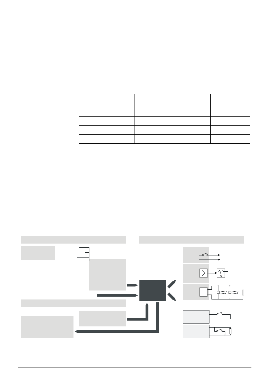
17.2 Means of linking
Any statuses of entry nodes can be linked to control ZONES
Normally, only 1 control ELEMENT is contained in 1 control ZONE (= control
output)
A user text is allocated to each control ZONE
E3G050
K3I110
E3L020
E3G070
E3G060
Acquisition level
Control level
AREA
SECTION
ZONE
Operating level
Acknowledgement circuit
not
monitored
monitored
addressable
collective
Statuses:
- alarm
- info
- switched off
- on detector TEST
- fault
- etc.
Control
ZONE
Operatable functions:
- switch on/off
- activate/de
-activate
Visible statuses:
- active
- switched off
- executed ('Acknowledgem.')
- fault
Digital input
‘active’