Technical references, Tie-line function, Free input and output assignment function – Sony MK7807V1 User Manual
Page 154: Name setting function
152
Technical References
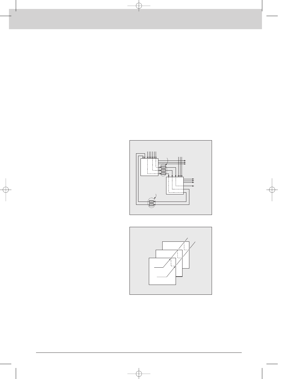
Tie-line function
This function automatically selects signal paths
across multiple routing switchers. This function is
used to effectively utilize external devices between
routers, or to increase the number of
inputs/outputs. Up to 255 signal paths connecting
specific inputs and outputs can be registered for
each group (source, net, and destination). When
the input and output are selected, the primary
station CPU automatically selects an unused
signal path. Signal paths can be set over multiple
levels (Figure 3). This function makes possible
the efficient system operation of complicated
signal paths through routing switchers without
having to separately activate the appropriate
crosspoints in each of these routers.
Free input and output assignment
function
Free assignment of inputs and outputs allows
sources and destinations on different levels to
be grouped under a single source or destination
name. For example the video, audio and time
code signals of VTR-001 do not have to be
assigned to the same channel on each level,
but could be assigned as, say, channel 1 of the video router, channel 10 of the audio router
and channel 12 of the time code router. This function provides a much more flexible signal-
handling environment.
Name setting function
Names can be set for Sources and Destinations in order to identify the signals connected.
The following two methods are available for setting names.
(1) “Type name (VTR, CAM, etc.) + Number”: 32 names each comprising up to four letters and
three numbers.
(2) “Descriptive name (REPORT_FROM_LA, etc)”: Name made of up to 16 Latin alphanumeric
characters.
Eight group of data can be registered within the primary station with each group containing
160 descriptive names. This data can be sent and displayed on UMDs (Under Monitor
Displays) and remote control panels.
To digital
production
facilities
To analog
production
facilities
D/A converter
Analog Matrix Switcher
(LEVEL-1)
A/D converter
Digital Matrix Switcher
(LEVEL-2)
Figure-3
Tie-Line Function Concept Diagram
Level-1
(Video)
Level-2
(Audio)
Level-3
(Time Code)
VTR 001
CUT 004
1
3
10
7
12
4
Figure-4
Free Input and Output Assignment
*SGC_0145-0161 02.3.19 5:37 PM Page 152