Contract or – Skuttle Indoor Air Quality Products 60-2 User Manual
Page 19
CONTRACT
OR
Wiring the Air Mover
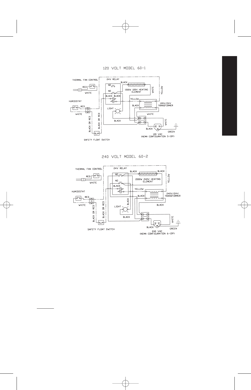
Figure 5 - Wiring diagram for Model 60-1 and F60-1 (120 volt) Steam Humidifiers.
Figure 6 - Wiring diagram for Model 60-2 and F60-2 (240 volt) Steam Humidifier.
Due to the high-capacity design of Skuttle Steam Humidifiers, it is nec-
essary that the furnace air mover be wired to function in cooperation with
the humidifier’s operation (see Figures 7, 8A and 8B, pgs. 20 & 21). To
achieve synchronization and prevent condensation inside the duct-work,
Skuttle has incorporated a thermostatic sensor for low-voltage applica-
tions into the design. The sensor/switch, attached to the humidifier wall,
is a sealed unit, preset to turn on when the humidifier’s water temperature
reaches 170°F, and to turn off when it falls below 120°F.
NOTE: Even if the heating and cooling system’s fan switch is left in the
“ON” position, it cannot be assumed that the homeowner will allow
constant operation of the fan motor. Therefore, it is necessary to install
a fan sail switch or a Skuttle A50 relay, mounted in the system supply
duct and wired into the low-voltage humidistat circuit. This prohibits the
humidifier from operating if the furnace fan fails to function or if it is man-
ually turned off.
19