Rj-21 port pin assignments, Figure b-4 – SMC Networks VDSL2 User Manual
Page 72
C
ABLES
B-8
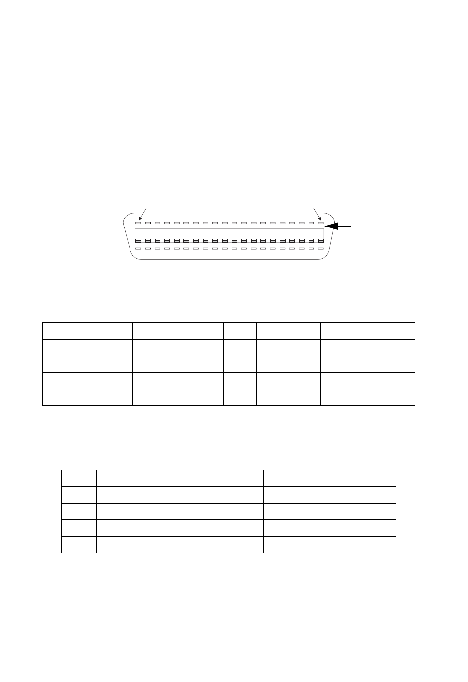
RJ-21 Port Pin Assignments
The RJ-21 ports are designed to aggregate 24 POTS/VDSL lines, although
only 16 lines are implemented for this switch. Each wire pair must be
attached to the RJ-21 connector in a specific orientation detailed below.
The following tables show the pin assignments.
Figure B-4 RJ-21 Port Pins
The VDSL Line connector is designed to aggregate 16 VDSL ports. The
following table shows the pin assignments.
Table B-3 RJ-21 Port Pin Assignments (PBX/MDF connector)
Pins
Circuit
Pins Circuit
Pins
Circuit
Pins Circuit
48,49 1, Ring/Tip 42,43 5, Ring/Tip 36,37 9, Ring/Tip
30,31 13, Ring/Tip
22,23 2, Ring/Tip 16,17 6, Ring/Tip 10,11 10, Ring/Tip 4,5
14, Ring/Tip
45,46 3, Ring/Tip 39,40 7, Ring/Tip 33,34 11, Ring/Tip 27,28 15, Ring/Tip
19,20 4, Ring/Tip 13,14 8, Ring/Tip 7,8
12, Ring/Tip 1,2
16, Ring/Tip
Table B-4 RJ-21 Port Pin Assignments (VDSL Line connector)
Pins
Circuit
Pins
Circuit
Pins
Circuit
Pins
Circuit
48,49
Port 1
42,43
Port 5
36,37
Port 9
30,31
Port 13
22,23
Port 2
16,17
Port 6
10,11
Port 10
4,5
Port 14
45,46
Port 3
39,40
Port 7
33,34
Port 11
27,28
Port 15
19,20
Port 4
13,14
Port 8
7,8
Port 12
1,2
Port 16
1
25
female
connector