Connecting to the console port, Wiring map for serial cable, Connecting to the console port -10 – SMC Networks VDSL2 User Manual
Page 48: Wiring map for serial cable -10, Table 3-2 wiring map for serial cable -10, Figure 3-9, Serial port (rj-45) pin-out -10
I
NSTALLING
THE
S
WITCH
3-10
and without disrupting the operation of the devices attached to the
unit.
Connecting to the Console Port
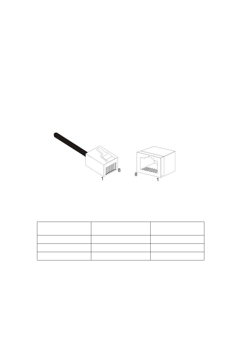
The RJ-45 serial port on the switch’s front panel is used to connect to the
switch for out-of-band console configuration. The on-board configuration
program can be accessed from a terminal or a PC running a terminal
emulation program. The pin assignments used to connect to the serial port
are provided in the following table.
Figure 3-9 Serial Port (RJ-45) Pin-Out
Wiring Map for Serial Cable
Table 3-2 Wiring Map for Serial Cable
Switch’s 8-Pin
Serial Port
Null Modem
PC’s 9-Pin
DTE Port
6 RXD (receive data)
<----------------------------
3 TXD (transmit data)
3 TXD (transmit data)
----------------------------->
2 RXD (receive data)
5 SGND (signal ground) ------------------------------
5 SGND (signal ground)
No other pins are used.