Connecting to the punch-down blocks, Connecting to the punch-down blocks -2, Figure 4-1 – SMC Networks VDSL2 User Manual
Page 52: Aking, Etwork, Onnections
M
AKING
N
ETWORK
C
ONNECTIONS
4-2
each end. Typically 24 AWG (100 ohm)/0.5 mm wire provides
better performance than 26 AWG (100 ohm)/0.5 mm wire.
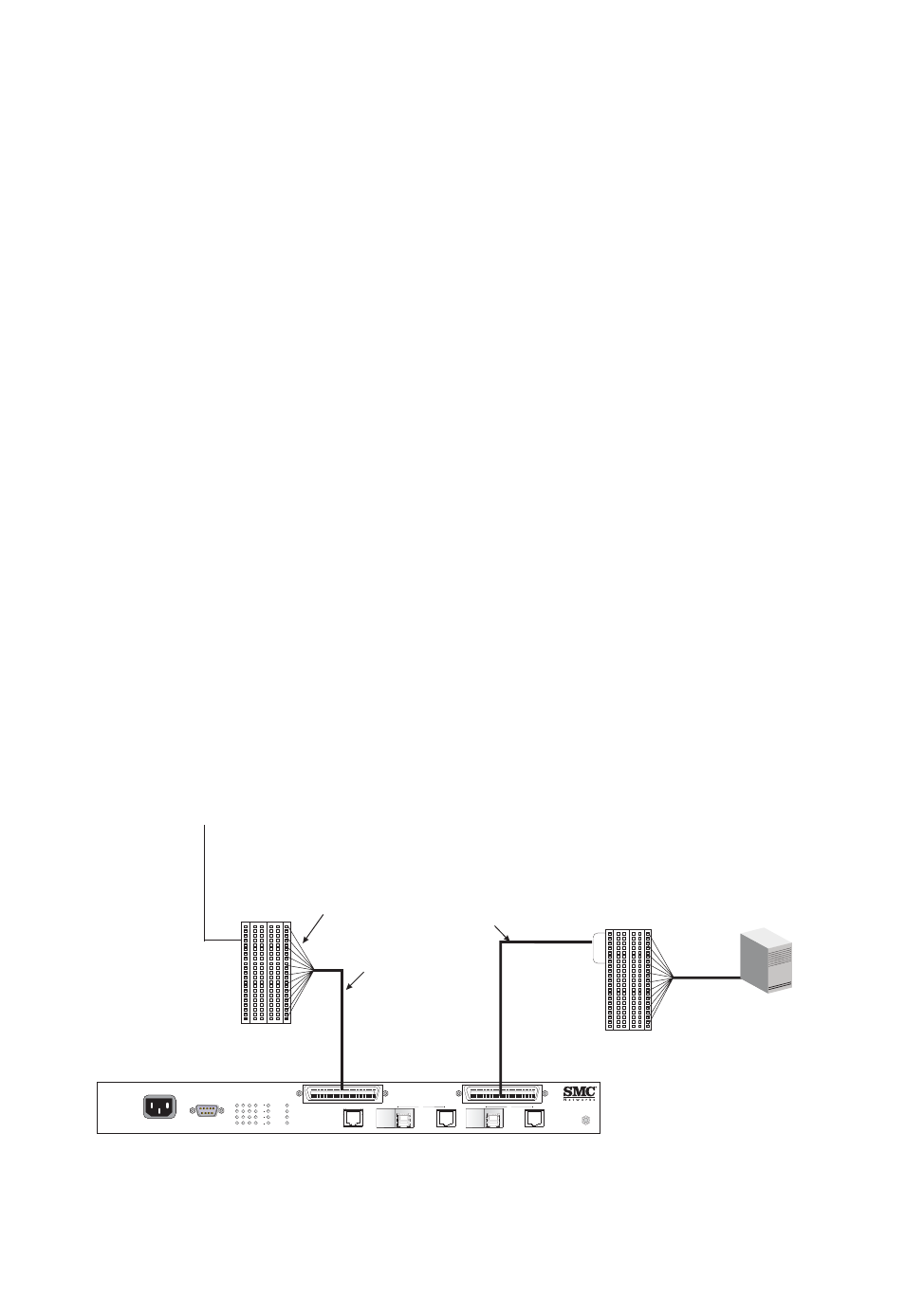
Connecting to the Punch-down Blocks
The switch connects directly to the PBX and building’s phone-line
punch-down block with RJ-21 connectors. Follow the steps listed below to
connect the switch.
1. Connect one RJ-21 cable from the PBX/MDF to the RJ-21 connector
on the rear of the switch labeled “POTS.”
2. Connect another RJ-21 cable from the punch-down block to the RJ-21
connector on the rear of the switch labeled “VDSL.” Note that the
connection to the punch down block usually requires punching down
the free wires from the RJ-21 cable.
The RJ-21 ports on punch-down blocks must be wired to match the pin
assignments of ports on the back of the switch. To ensure that your cables
are properly wired, refer to “RJ-21 Port Pin Assignments” on page B-8.
Note: If you are using a patch panel, connect the RJ-21 ports on the back
of the switch directly to the corresponding ports on the patch
panel, and then manually wire each pair (up to 16) from the patch
panel to the punch-down blocks.
Figure 4-1 Connecting to the Punch-down Blocks
100 240V 50 60Hz 1A
-
-
Console
1
2
3
4
5
6
7
8
9
10
11
12
14
13
15
16
17
E
O
18
E
O
Power
Fault
Diag
Mgmt
Line
Mgmt
O
E
17
O
E
18
POTS
ESD PORT
S M C 7 8 1 6 M
V S W
/
TigerAccess
EE Switch
TM
RJ-21
Cable
PBX/MDF
Connector
PBX
Punch-down Block
with RJ-21 Connector
Building’s Phone-line
Punch-down Block
Free
Wiring
Twisted-pair
Connection
to CPE
RJ-21
Cable