Chapter 3 installing the switch, Preparing the site for vdsl/pots connections, Installing the switch -1 – SMC Networks VDSL2 User Manual
Page 39: Preparing the site for vdsl/pots connections -1, Figure 3-1, Wiring before vdsl switch installation -1, Hapter, Nstalling, Witch
3-1
C
HAPTER
3
I
NSTALLING
THE
S
WITCH
Preparing the Site for VDSL/POTS Connections
In multi-tenant buildings, phone lines from the service provider enter the
site and are terminated at a location referred to as the MPOE (Minimum
Point of Entry). The MPOE is the “demarcation” point where the service
provider’s cables end and that of the building’s owner/customer begins.
An MPOE typically consists of two sets of punch-down blocks; one from
the service provider, and the other from the customer. The customer’s
punch-down blocks are connected to PBX or MDF equipment in the
building. A PBX may have either analog or digital cards that provide the
phone lines to individual end users. The PBX lines are usually connected
to the end users through another set of punch-down blocks or patch
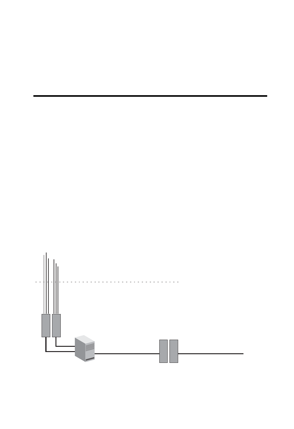
panels. The following figure displays the normal wiring before installing
the VDSL switch.
Figure 3-1 Wiring before VDSL Switch Installation
Punch-Down Blocks
Connecting to Clients
PBX
Telephone Line
from Central Office
Existing Phone
Lines to Clients
Upper Floors
Basement
MPOE
Customer s
Punch-Down
Blocks
'
Service Provider s
Punch-Down
Blocks
'