Left to right, Ri ght side, Dr iv e un it left side – Jackson AJ-100CS User Manual
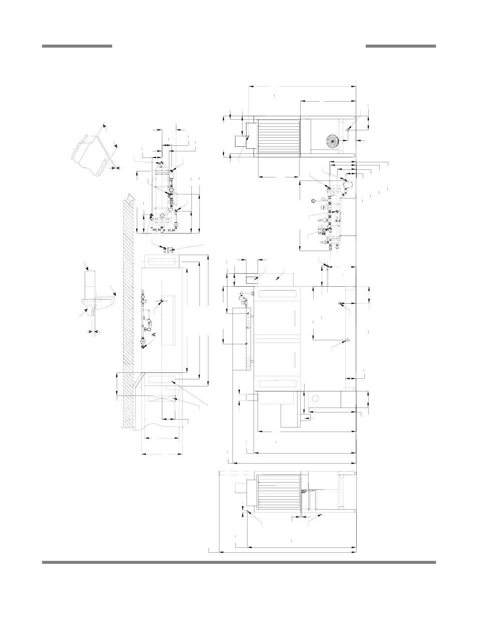
Page 17: Recommended table fabr ication, Front view, Aj-64 steam - left to right 9
Ri
ght Side
34 [864mm]
21 [533mm]
25 [635mm]
12 [307mm]
25 [635mm]
Table to Table
Over
all
D
ish C
learance
B
Dr
iv
e
Un
it
Left Side
66
1
2
[1692mm]
1
2
[15mm]
84 [2134mm]
With D
oors Open
R
ear
of
Machine
1 [25mm]
3/4" (
19 mm)
Table Tur
ndow
n
Flange 3/4" Max
21" (
533 mm)
Ra
ck Ra
il He
ig
h
t
A
bove D
ishtable
1/4" (
6
mm)
-
5/16" (8mm)
Ra
ck Ra
il
Tub
Table
U
s
e S
ilicone S
ealer
B
e
tw
een Table and
Lip of Machine to
P
revent Leakage
Recommended Table Fabr
ication
N
o
te: Tub Will A
ccept
a Table Flange
U
p
to 24 7/8"
(632 mm)
4" (
102 mm)
w
ide x 16" (406 mm)
long cutout in V
ent C
o
w
l/S
plash
S
h
ield. S
h
ipped w
ith C
o
ver P
late.
Floor
S
ink Or D
rain
With 3" (
76 mm)
Minimum D
rain Line
25 [637mm]
64 [1626mm]
72 [1829mm]
80 [2032mm]
8 [204mm]
14 [355mm]
Sc
ra
p
Tr
ough
Mi
ni
mu
m
21 [535mm]
65
1
2
[1665mm]
A
Dri
v
e
Un
it
Front View
75
1
2
[1915mm]
62
1
2
[1588mm]
29 [737mm]
6
1
2
[165mm]
10 [254mm]
7 [178mm]
D
E
C
4 [102mm]
8 [203mm]
14 [354mm]
Mi
ni
mu
m
10"
H
igh
Table
B
a
cksplash
Sc
ra
p
Tr
ough
60
1
4
[1528mm]
32
3
4
[833mm]
35 [891mm]
5 [127mm]
8
1
2
[218mm]
C
Left to Right
Legend
A
-
Machine w
a
ter
inlet 3/4" N
P
T 180°F
H
i-
temp,140°
F Low
-temp minimum
B
-
E
lectr
ical connection
C
-
D
rain connection 1-1/2" N
P
T
D
-
V
ent collar
- Optional
E
-
V
ent cow
l standard
F -
3/4" N
P
T S
team connection
G -
3/4" N
P
T C
ondensate return
H
-
S
team electr
ical connection
J -
1" N
P
T S
team connection
K
-
3/4" C
ondensate connection
L -
3/4" N
P
T Incoming 110°F w
a
ter
connection
M -
3/4" N
P
T 180°
F w
a
ter to dishmachine.
N
o
te: A
ll ver
tical dimensions are +/- 1/2"
fr
om floor
due to adjustable bullet feet.
12
1
2
[316mm]
F
17
1
2
[442mm]
6
1
2
[162mm]
11
1
2
[295mm]
15
3
4
[400mm]
16
1
2
[417mm]
43 [1092mm]
11
1
4
[285mm]
13
1
2
[345mm]
23
3
4
[604mm]
38 [966mm]
6
1
4
[159mm]
5
3
4
[148mm]
4
1
4
[110mm]
8
1
2
[218mm]
H
J
L
M
K
L
H
J
M
F
B
10 [255mm]
G
10
1
2
[264mm]
24
1
2
[622mm]
SECTION 1: SPECIFICATION INFORMATION
AJ-64 STEAM - LEFT TO RIGHT
9
AJ-64 Conveyor Series Technical Manual 7610-003-30-93
Issued: 05-02-2006 Revised: 09-29-2007