Left to r ight, Rig h t side, Dr iv e uni t left sid e – Jackson AJ-100CS User Manual
Page 15: Fr ont vi e w
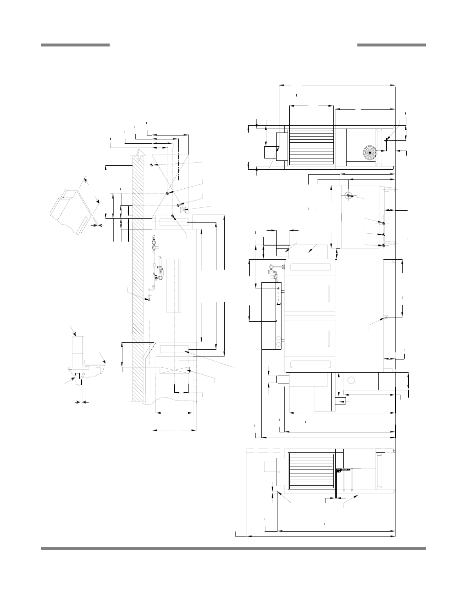
Rig
h
t Side
34 [864mm]
21 [533mm]
25 [635mm]
12 [307mm]
25 [635mm]
Table to Table
O
v
er
all
D
is
h
C
lear
ance
20
3
4
[527mm]
8
3
4
[222mm]
11
3
4
[298mm]
14
3
4
[375mm]
6 [154mm]
30 [763mm]
14 [357mm]
7
1
4
[185mm]
1
1
4
[35mm]
6 [152mm]
31
1
4
[795mm]
6
1
2
[165mm]
26
1
2
[673mm]
B
Left to R
ight
Dr
iv
e
Uni
t
Left Sid
e
66
1
2
[1692mm]
1
2
[15mm]
84 [2134mm]
With D
oor
s O
pen
R
ear
of
Ma
ch
in
e
Legend to D
raw
ing
A
-
M
a
c
h
ine w
a
ter
inlet 3/4" N
P
T, 180°F
H
i-
tem
p,140°F Low
-t
emp minimum
B
-
E
lectr
ical connection
C
-
D
rain c
onnec
tion 1-
1/2" N
P
T
D
-
V
ent c
o
llar
-
O
p
tional
E
-
V
ent cow
l s
tandar
d
F -
3/4" N
P
T 180°F Water
Inlet for
w
a
sh tank
fill, final r
ins
e, & tank heating. Fr
om gas
boos
ter
heater
. Inter
c
onnecting hose
pr
ov
ided by
manufactur
e
r.
G
-
3/4" N
P
T 140°F Water
inlet for
gas
boos
ter
heater
.
H
-
3/4" N
P
T 180°F Water
O
u
tlet
connec
tion to line on dishmachine.
C
onnec
tion hos
e pr
ov
ided by
m
anufactur
e
r.
J
-
3/4" N
P
T G
a
s C
onnec
tion
K
-
4" O
D
V
ent pipe connection. Flue to
be ins
talled to meet loc
a
l c
odes
by
ins
talling contr
a
ctor
.
N
o
te: A
ll v
e
rt
ic
al dim
ensions ar
e +/-
1/2" fr
om
floor
due to adjus
table bullet feet.
1 [25mm]
K
J
H
G
3/4" (
19 mm)
Table Tur
ndow
n
Flange 3/4" Max
21" (
533 mm)
Ra
ck
Ra
il He
ig
h
t
A
bove D
is
h
table
1/4" (
6
m
m
) -
5/16" (
8
mm)
Ra
c
k
Ra
il
Tub
Table
U
s
e Silic
one Sealer
B
e
tw
een Table and
Lip of M
a
chine to
P
revent Leakage
Recommen
d
e
d
Tab
le Fab
ricat
io
n
N
o
te: Tub Will Ac
cept
a Table Flange
U
p
to 24 7/8"
(632 mm)
F
4" (
102 m
m
) w
ide x
16" (
406 mm)
long cutout in V
ent C
o
w
l/S
plash
S
h
ield. S
h
ipped w
ith C
o
ver
P
late.
Floor
S
ink O
r D
rain
With 3" (
76 mm)
M
inim
u
m
D
rain Line
25 [637mm]
64 [1626mm]
72 [1826mm]
80 [2032mm]
8 [204mm]
14 [355mm]
Sc
ra
p
Tr
ough
Mi
ni
mu
m
21 [535mm]
36 [914mm]
K
J
H
G
65
1
2
[1665mm]
A
Dr
iv
e
Un
it
Fr
ont Vi
e
w
75
1
2
[1915mm]
62
1
2
[1588mm]
29 [737mm]
6
1
2
[165mm]
10 [254mm]
7 [178mm]
D
E
C
4 [102mm]
8 [203mm]
14 [354mm]
Mi
ni
mu
m
10"
Hi
gh
T
abl
e
Ba
cksp
la
sh
Scr
a
p
T
rough
60
1
4
[1530mm]
32
3
4
[833mm]
35 [891mm]
5 [127mm]
8
1
2
[218mm]
C
24
1
2
[622mm]
SECTION 1: SPECIFICATION INFORMATION
AJ-64 GAS - LEFT TO RIGHT
7
AJ-64 Conveyor Series Technical Manual 7610-003-30-93
Issued: 05-02-2006 Revised: 09-29-2007