Parts identification – JVC TH-A10 User Manual
Page 13
11
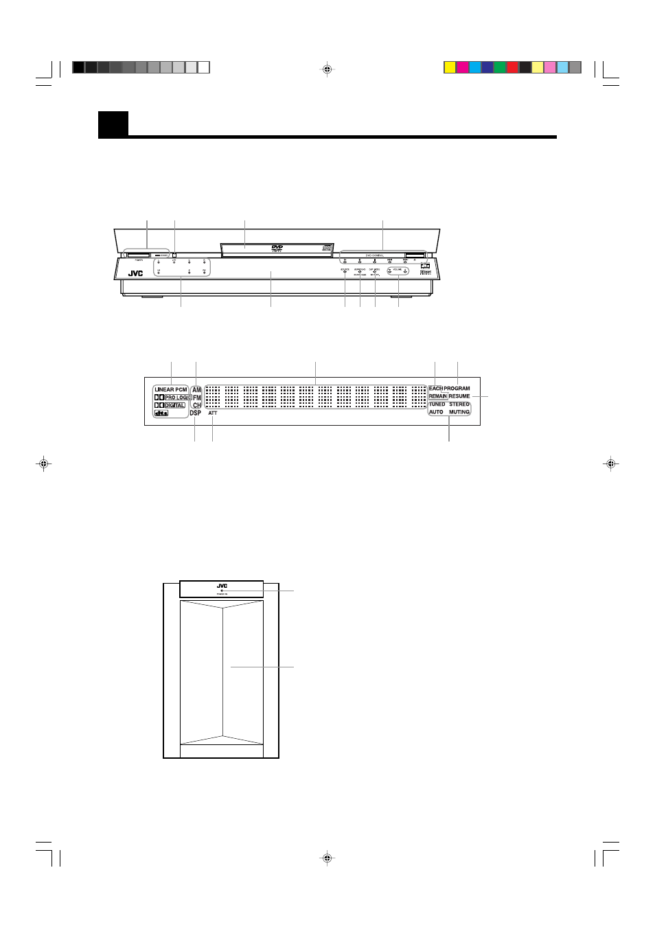
Parts Identification
Become familiar with the buttons and controls on the unit before use. Refer to the pages in parentheses for details.
Center unit ———————————————————————————————————————
1
2
3
4
5
6
7
8
p
1 POWER buftton and
STANDBY lamp (16)
2 Remote sensor (10)
3 Disc tray (22)
4 DVD CONTROL buttons
(22~24)
5 VOLUME +/ – button (16)
6 DSP MODE /INPUT ATT.
(19, 20, 21)
7 SURROUND/SOURCE
NAME (17, 21)
8 SOURCE (17)
9 Display window
p Audio channel lamp (19)
9
Display window
1
2
3
4
5
6
7
8
9
Front panel
1 Decord mode indicator (18)
2 Radio indicator (36)
3 Multi-information window
Display time and status information.
4 Time selection indicator (34)
5 PROGRAM indicator (34)
Powered sub-woofer —————————————————————————————————————
6 RESUME indicator (24)
7 Radio reception mode indicator (37)
8 ATT. indicator (19)
9 DSP indicator (20)
1
2
1 POWER ON lamp (16)
2 Speaker
TH-A10[J]1/1
00.2.24, 14:47
11
- XV-THA75R (76 pages)
- TH-A85 (68 pages)
- TH-M45 (134 pages)
- TH-A25 (48 pages)
- TH-A25 (50 pages)
- TH-V70R (84 pages)
- TH-A9R (65 pages)
- TH-A10R (68 pages)
- TH-A35 (63 pages)
- SP-WA30 (64 pages)
- TH-S2 (44 pages)
- TH-A5R (1 page)
- DD-8 (60 pages)
- QP-F30ALE (40 pages)
- SP-THS5S (48 pages)
- XV-THBD50 (48 pages)
- DVD DIGITAL CINEMA SYSTEM TH-A30R (64 pages)
- SP-THS55C (100 pages)
- Th-g41 (3 pages)
- TH-M505/TH-M501 (52 pages)
- SP-THG51F (29 pages)
- TH-C5 (59 pages)
- TH-C6 (48 pages)
- SP-PWS77 (46 pages)
- TH-S5 (48 pages)
- RX-ES9SL (45 pages)
- XV-THV70R (84 pages)
- XV-THS7 (48 pages)
- XV-THG31 (28 pages)
- SP-THS11C (43 pages)
- SP-THC3F (44 pages)
- EX-D11 (86 pages)
- TH-D8 (38 pages)
- XV-THG41 (29 pages)
- TH-R3 (100 pages)
- SP-PWA9 (67 pages)
- SP-THS11BF (40 pages)
- SP-THC60F (48 pages)
- TM-A9U (8 pages)
- DLA-RS1 (50 pages)
- SP-THD7S (43 pages)
- SP-THM45S (68 pages)
- XV-THA35 (68 pages)
- TH-S66 (49 pages)
- TH-M508 (52 pages)