How to use set-up menu, Cont.) 7 functions and adjustment range of items – JVC TM-1011G User Manual
Page 12
12
7 HOUR METER X100h
Displays the total usage time of the monitor in
hundred-hour units.
• 000
O 655
NOTES:
• When the timer passes 655, it returns to 000.
• The timer does not count usage time under one hour.
PICTURE SUB ADJ.
The standard value (“00”) of
the picture adjustment is
initially set at the factory.
You can adjust the standard
value as you want.
7 CONTRAST
• –20
O 00 O +20
7 BRIGHT
• –20
O 00 O +20
7 CHROMA
• –20
O 00 O +20
7 PHASE
• –20
O 00 O +20
COLOR TEMP./BAL.
Sets or adjusts the color
temperature and white
balance.
NOTE:
• Use the five items indicated with
mark to make fine
adjustments between the monitors.
7 COLOR TEMP.
Selects the color temperature.
HIGH:
Sets the color temperature to 9300.
LOW:
Sets the color temperature to 6500.
7 BLUE DRIVE
Adjusts the blue drive level.
• MIN
O 000 O MAX (in 127 grades)
7 RED DRIVE
Adjusts the red drive level.
• MIN
O 000 O MAX (in 127 grades)
7 GREEN CUTOFF
Adjusts the green cut-off point.
• MIN
O MAX (in 155 grades)
How to Use SET-UP MENU
(cont.)
7Functions and Adjustment Range of Items
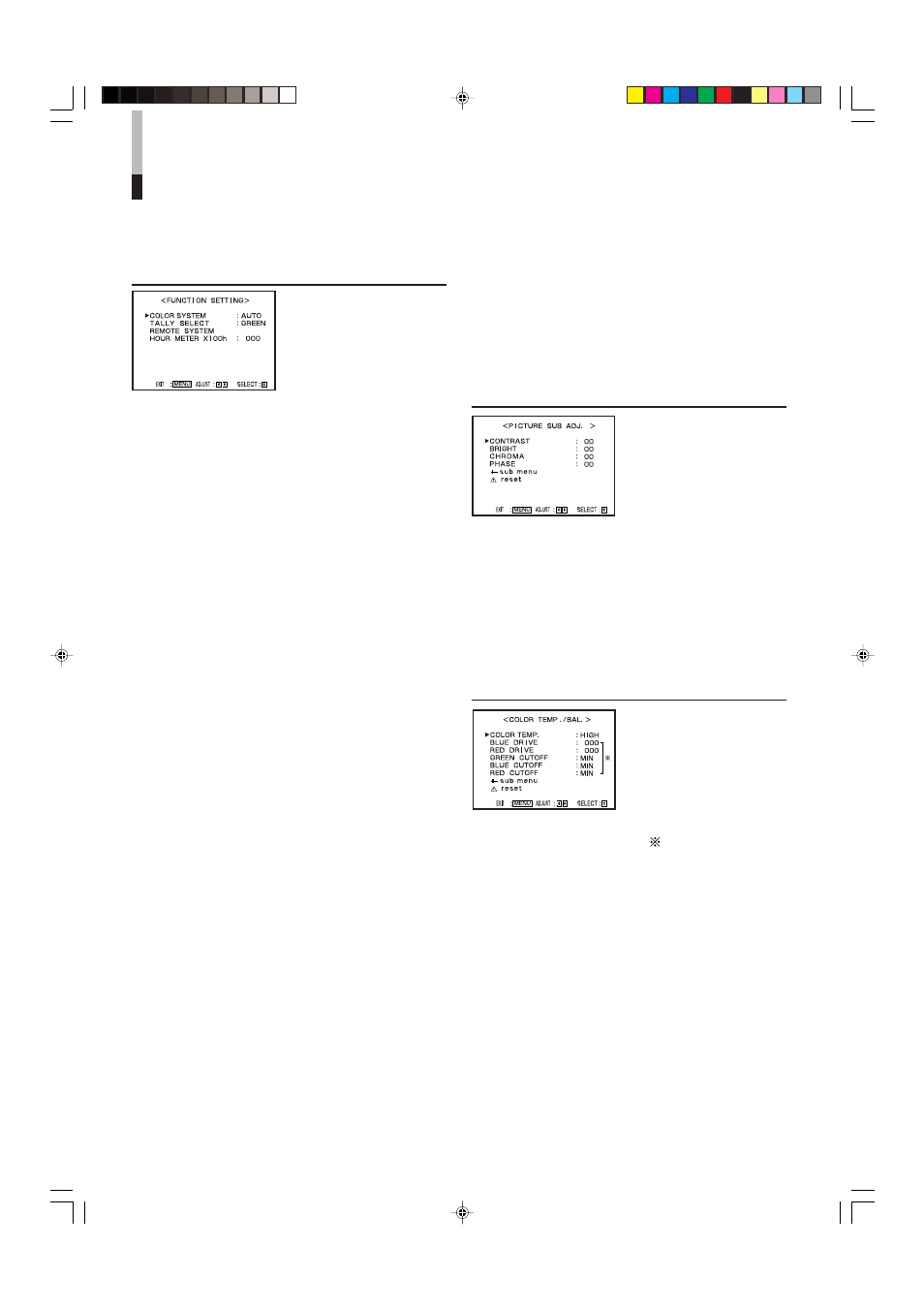
FUNCTION SETTING
Sets the control systems for
the COLOR SYSTEM,
colors of the tally lamp, and
MAKE/TRIGGER terminal.
• Can be also used to check
the amount of time that the
monitor has been used.
7 COLOR SYSTEM
Selects the color system.
AUTO:
Changes NTSC and PAL automatically.
NTSC:
Keeps the color system NTSC.
PAL:
Keeps the color system PAL.
NOTE:
• Normally select “AUTO.” However, if the input signal is
unstable, select “NTSC” or “PAL.”
7 TALLY SELECT
Selects the color of the tally lamp on the upper right
of the front panel.
GREEN: The tally lamp lights in green.
RED:
The tally lamp lights in red.
NOTES:
• “TALLY SELECT” does not appear on the menu when
both of the following conditions are applied:
– When selecting “TA. SEL” to a pin terminal of the
MAKE/TRIGGER terminal in “REMOTE SYSTEM” of
SET-UP MENU.
– When the external control is activated.
• The tally lamp is controlled using the MAKE/TRIGGER
terminal of the REMOTE (external control) terminals.
☞ “REMOTE SYSTEM” below, “How to Use the External
Control” on pages 14 and 15
7 REMOTE SYSTEM
Sets the MAKE/TRIGGER terminal.
☞ “How to Use the MAKE/TRIGGER Terminal” on pages
14 and 15
• CONTROL FORM:
Selects the control system for the MAKE/
TRIGGER terminal.
MAKE: Selects the make contact system as
the external control method.
TRIG.: Selects the trigger system as the
external control method.
SET:
You can apply the functions to the 1st
to 6th pin terminals of the MAKE/
TRIGGER terminal as you want.
• PORT F1 – PORT F6:
Selects the function to be applied to the 1st to 6th
pin terminals of the MAKE/TRIGGER terminal.
☞ “How to Use the MAKE/TRIGGER Terminal” on page 14
NOTE:
• You can set “PORT F1” – “PORT F6” only when
“CONTROL FORM” is set to “SET.”
En_11-20_TM-1011G.p65
06.2.14, 22:37
12