B mechanical drawings, Mechanical drawings, Mechanical drawing list – Intel 5400 Series User Manual
Page 57: Appendix b, S. refer to, Bmechanical drawings
Quad-Core Intel® Xeon® Processor 5400 Series TMDG
57
Mechanical Drawings
B
Mechanical Drawings
The mechanical drawings included in this appendix refer to the thermal mechanical
enabling components for the Quad-Core Intel® Xeon® Processor 5400 Series.
Note:
Intel reserves the right to make changes and modifications to the design as necessary.
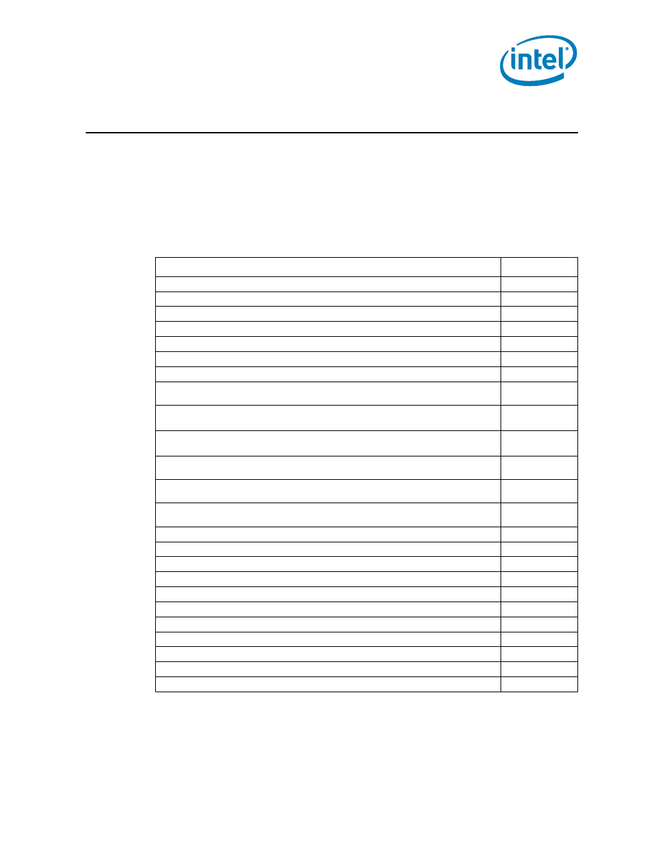
Table B-1. Mechanical Drawing List
Drawing Description
Figure Number
“2U CEK Heatsink (Sheet 1 of 4)”
“2U CEK Heatsink (Sheet 2 of 4)”
“2U CEK Heatsink (Sheet 3 of 4)”
“2U CEK Heatsink (Sheet 4 of 4)”
“Baseboard Keepout Footprint Definition and Height Restrictions for Enabling Components
“Baseboard Keepout Footprint Definition and Height Restrictions for Enabling Components
“Baseboard Keepout Footprint Definition and Height Restrictions for Enabling Components
“Baseboard Keepout Footprint Definition and Height Restrictions for Enabling Components
“Baseboard Keepout Footprint Definition and Height Restrictions for Enabling Components
“Baseboard Keepout Footprint Definition and Height Restrictions for Enabling Components
“1U CEK Heatsink (Sheet 1 of 4)”
“1U CEK Heatsink (Sheet 2 of 4)”
“1U CEK Heatsink (Sheet 3 of 4)”
“1U CEK Heatsink (Sheet 4 of 4)”
“Active CEK Thermal Solution Volumetric (Sheet 1 of 3)”
“Active CEK Thermal Solution Volumetric (Sheet 2 of 3)”
“Active CEK Thermal Solution Volumetric (Sheet 3 of 3)”
“1U Alternative Heatsink (1 of 4)”
“1U Alternative Heatsink (2 of 4)”
“1U Alternative Heatsink (3 of 4)”