Intel AR-B1760 User Manual
Page 26
INSTALLATIONS
22
AR-B1760 User’s Manual
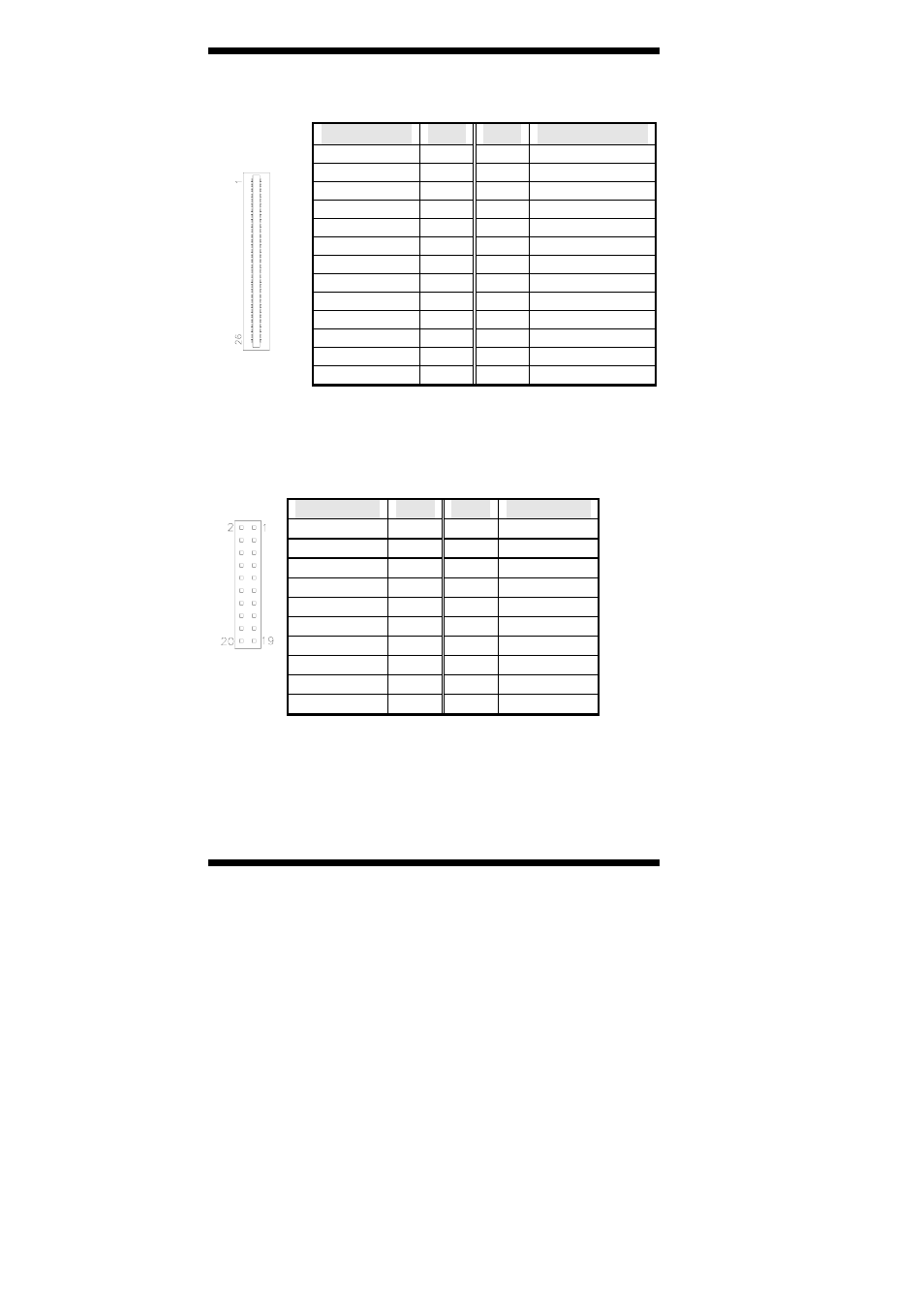
J10: Floppy Drive Connector
J10 is a slim 26-pin connector and will support up to 2.88MB FDD.
Signal Name
Pin #
Pin #
Signal Name
VCC 1
2 INDEX
VCC 3
4
DRV_SEL
VCC 5
6 DSK_CH
NC 7
8 NC
NC 9
10
MOTOR
DINST 11
12
DIR
NC 13
14 STEP
GND 15
16 WDATA
GND 17
18 WGATE
GND 19
20 TRACK
NC 21
22 WPROT
GND 23
24 RDATA
GND 25
26 SIDE
J11, J12: Serial ATA Connectors (option)
J13, J9: LVDS Connectors (1st channel, 2nd channel)
The LVDS connectors are composed of the first channel (J13) and
second channel (J9) to support 24-bit or 48-bit.
Signal Name
Pin #
Pin #
Signal Name
TX0- 2
1 TX0+
Ground 4 3 Ground
TX1- 6
5 TX1+
5V/3.3V 8 7 Ground
TX3- 10
9 TX3+
TX2- 12
11 TX2+
Ground 14 13 Ground
TXC- 16
15 TXC+
5V/3.3V 18 17 ENABKL
+12V 20
19 +12V
- 41210 (64 pages)
- 8xC251TQ (20 pages)
- ENTERPRISE PRINTING SYSTEM (EPS) 4127 (84 pages)
- U3-1L (20 pages)
- 80960HA (104 pages)
- X58 (54 pages)
- ESM-2850 2047285001R (91 pages)
- ATOM US15W (54 pages)
- D915GVWB (4 pages)
- XP-P5CM-GL (28 pages)
- AX965Q (81 pages)
- CORETM 2 DUO MOBILE 320028-001 (42 pages)
- CV700A (63 pages)
- 80C188EA (50 pages)
- X25-M (28 pages)
- XP-P5IM800GV (26 pages)
- IB868 (60 pages)
- D865GVHZ (88 pages)
- IB865 (64 pages)
- Altera P0424-ND (1 page)
- 8086-2 (30 pages)
- IXDP465 (22 pages)
- IWILL P4D (104 pages)
- GA-8I955X PRO (88 pages)
- FSB400 (PC2100) (96 pages)
- D845GLAD (4 pages)
- NAR-3041 (1 page)
- 87C196CA (136 pages)
- G52-M6734XD (74 pages)
- A96134-002 (10 pages)
- Express Routers 9000 (8 pages)
- 82540EP (45 pages)
- D865GLC (94 pages)
- IB850 (69 pages)
- MB898RF (62 pages)
- Arima LH500 (78 pages)
- V09 (33 pages)
- I/O Processor (22 pages)
- M600 (110 pages)
- SE7520JR2 (63 pages)
- SERVER BOARD S5520HCT (30 pages)
- Extensible Firmware Interface (1084 pages)
- GA-8IPXDR-E (70 pages)
- D845EBG2 (4 pages)
- AW8D (80 pages)