Intel SR6850HW4 User Manual
Page 27
Intel® Server Platform SR6850HW4 TPS
System Overview
Revision 1.0
Intel order number D23151-001
15
qualified technical individuals should access the processor and non-hot-plug I/O
areas while the system is energized. Power cords should be removed from the
system before accessing non-hot-plug areas.
2.5.11.1
System Power Budget
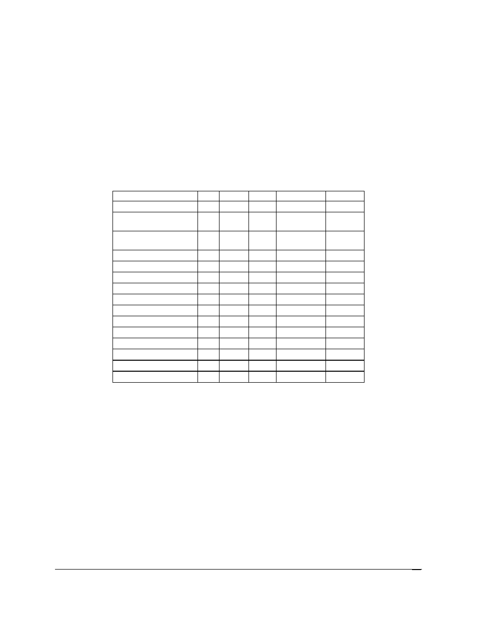
Table 3 shows a summary of the system power budget.
The power budget lists each major
voltage rail in columns and each major subsystem of the product in rows.
The worst-case
power per subsystem is listed for each voltage rail.
The total power per voltage rail, the
power supply specification, and the margin available are shown at the bottom of the table.
Table 3. System Power Budget
Notes:
1. 3.3V and 5V are derived from the 12V single switched output of the power
supply modules.
The
12V column includes the 3.3V and 5V power.
2. 3.3V
stby
is the standby output of the power supply modules.
Subsystem
Qty
+3.3V
+5V
+12V (Total)
+3.3V
stby
Mainboard 1
49W
27W
147W
15W
SCSI Backplane Board
Board
1
2.5W
2.5W
Front Panel I/O Board
and front panel
1ea 2W
2W
Processors 4
448W
Memory 16
4W
192W
Fans 6
173W
Hard disk drives
10
28W
84W
½inches optical drive
1
1W
6W
SCSI tape device
1
3W
7W
PCI-X* slots
3
45W
PCI Express* slots
4
80W
Fibre channel module
1
15W
System Total
1189.5W
15W
Power subsystem spec
1570W
16.5W
Margin
380.5W
1.5W