4 external chassis features - rear – Intel SR6850HW4 User Manual
Page 22
System Overview
Intel® Server Platform SR6850HW4 TPS
Revision
1.0
Intel order number D23151-001
10
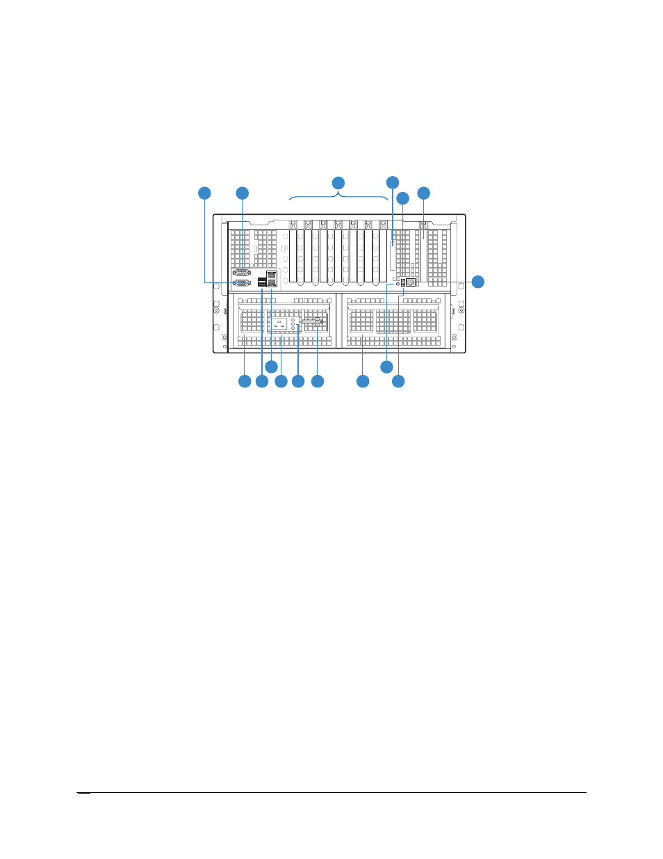
2.4 External Chassis Features - Rear
Figure 5
shows the rear view of the Server Platform SR6850HW4. The user-accessible
connectors, PCI slots, and power supply modules located at the rear of the system are described
in the following sections.
TP01507
A
B
E
D
F
1
7
4
3
2
5
6
C
H
K
J
I
L
G
M
O
N
P
A Video
connector
B
Serial port connector
C PCI
slots
Slot 1
PCI Express* x8 (hot-plug)
Slot 2
PCI-X* 133Mhz, 64-bit (hot-plug)
Slot 3
PCI Express x4 (hot-plug)
Slot 4
PCI Express x4 (hot-plug)
Slot 5
PCI Express x4 (hot-plug)
Slot 6
PCI-X 100Mhz, 64-bit (not hot-plug)
Slot 7
PCI-X 100Mhz, 64-bit (not hot-plug)
D
External SCSI connector
E
System ID LED (blue)
F
Fibre Channel Module slot (optional accessory)
G
Power supply unit
H
USB 2.0 ports (two)
I
LAN ports, RJ45 connector (LAN1 on top, LAN2 on bottom)
J
AC input power connector
K
Power supply unit status LEDs
L
Power cord retention featurek
M
Active fan power supply blank
N
System ID button
O
DC jack (not used)
P
Dedicated server management port, RJ45 connector (used with the IMM Advanced)
Figure 5. Rear View of the Server Platform SR6850HW4