29 icos, Installation, 38 functional flow wiring diagram – IDEAL INDUSTRIES ICOS HE18 User Manual
Page 29: 37 pictorial wiring diagram, Inst alla tion, Installation & servicing
29
icos -
Installation & Servicing
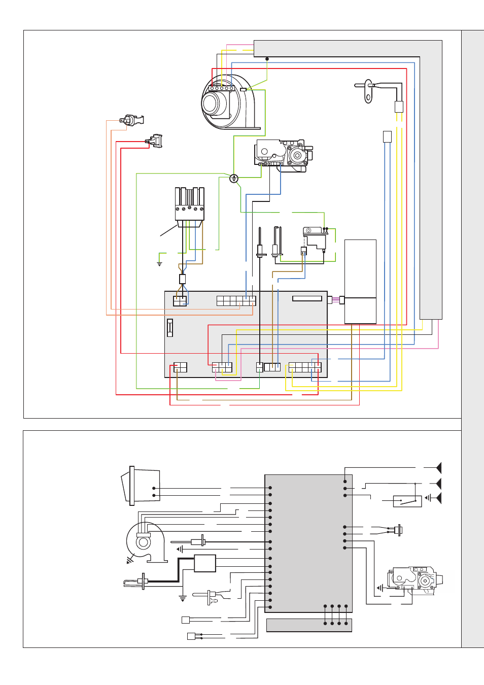
INSTALLATION
Spark generator
nm 8076
bk
b
br
bk
b
bk
r
b
v
b
r
br
b
r
r
b
r
r
r
or
or
or
or
b
pk
pk
y
y
y/g
y/g
Ferrite
y/g
y/g
y/g
y/g
y/g
y/g
bk
bk
Flue
thermistor
Overheat
thermostat
Flow
control
thermistor
Gas valve
ON /OFF
Switch
Service
connection
MAINS
SUPPLY
230V 50Hz
Permanent
black link
Fan
y
y
Chassis
earth y/g
Control PCB
Fused at
3.15ATL
bk
bk
y y
User
control
and
display
br
b
38 FUNCTIONAL FLOW WIRING DIAGRAM
Overheat
thermostat
1
2
br
r
r
bk
y
pk
b
Mains Switch
Flame detection
electrode
DC
Fan
Ignition electrode
CH return thermistor
(not fitted)
Control thermistor
DC Gas valve
b
v
bk
or
or
N
L
Control PCB
User PCB
y/g
r
r
y
b
y
b
nm 7201
br
y/g
br
bk
E
b
Flue thermistor
Spark generator
External switch e.g.
room'stat, programmer
37 PICTORIAL WIRING DIAGRAM
LEGEND
b - blue
bk - black
br - brown
gy - grey
or - orange
pk - pink
r
- red
v - violet
w - white
y - yellow
y/g - yellow/green
LEGEND
b - blue
bk - black
br - brown
gy - grey
or - orange
pk - pink
r
- red
v - violet
w - white
y - yellow
y/g - yellow/green
INST
ALLA
TION