Front panel, Led descriptions, Rj48 connectors j1 and j2 – Interphase Tech 4538 User Manual
Page 118
Front Panel
96
Interphase Corporation
Front Panel
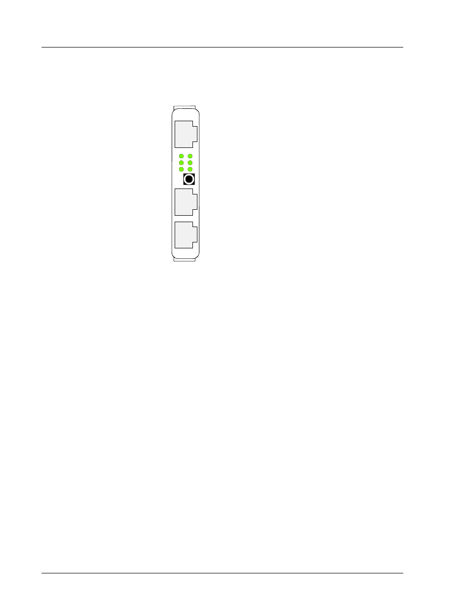
Figure 5-3. Connectors and Leds on front panel
LED Descriptions
CPU_LED1: Board user-programmable green LED controlled by PD(15)
CPU_LED2: Board user-programmable green LED controlled by PD(14)
CPU_LED3: Board user-programmable red LED controlled by PD(18)
CPU_LED4: Board user-programmable red LED controlled by PD(17)
LED1:Synchronization signal provided by the Framer 1 for Line 0
LED2:Synchronization signal provided by the Framer 2 for Line 1
LED3: LXT971 LED driver 1
LED4: LXT971 LED driver 2
LED5: LXT971 LED driver 3
LED6: User-programmable LED, CPU_LED6 controlled by PD(16)
RJ48 Connectors J1 and J2
J1 is tied to the first framer and J2 is tied to the second framer.
G@9$ÃÃG@9%
G@9"ÃÃG@9#
G@9 ÃÃG@9!
- 77<
- /LQH
- /LQH
- (WKHUQHW