English – Intel GA-4MXSV User Manual
Page 20
2 0
English
GA-4MXSV Motherboard
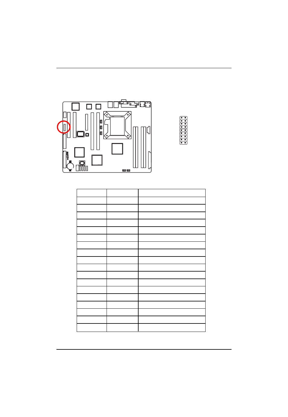
E ) F_Panel1 (2X9 Pins Front Panel connector)
Please connect the power LED, PC speaker, reset switch and power switch of your chassis
front panel to the F_PANEL connector according to the pin assignment above.
Pin No
Signal Name
Description
1
HD+
Hard Disk LED anode (+)
2
PWLED+
Power LED Signal anode (+)
3
HD-
Hard Disk LED cathode(-)
4
PWLED-
Power LED Signal cathode(-)
5
GND
Ground
6
PW+
Soft power connector anode (+)
7
RESET
Reset button
8
GND
Ground
9
N C
No Connect
10
N C
No Connect
11
N C
No Connect
12
LANA_LED-
LAN1 linked LED Signal
cathode(-)
13
LANB_LED-
LAN2 linked LED Signal
cathode(-)
14
N C
No connect
15
LANA_LED+
LAN1 linked LED Signal
anode (+)
16
LANB_LED+
LAN2 linked LED Signal
anode (+)
17
N C
No Connect
18
N C
No Connect
1 2
17 18
See also other documents in the category Intel Hardware:
- 41210 (64 pages)
- 8xC251TQ (20 pages)
- ENTERPRISE PRINTING SYSTEM (EPS) 4127 (84 pages)
- U3-1L (20 pages)
- 80960HA (104 pages)
- X58 (54 pages)
- ESM-2850 2047285001R (91 pages)
- ATOM US15W (54 pages)
- D915GVWB (4 pages)
- XP-P5CM-GL (28 pages)
- AX965Q (81 pages)
- CORETM 2 DUO MOBILE 320028-001 (42 pages)
- CV700A (63 pages)
- 80C188EA (50 pages)
- X25-M (28 pages)
- XP-P5IM800GV (26 pages)
- IB868 (60 pages)
- D865GVHZ (88 pages)
- IB865 (64 pages)
- Altera P0424-ND (1 page)
- 8086-2 (30 pages)
- IXDP465 (22 pages)
- IWILL P4D (104 pages)
- GA-8I955X PRO (88 pages)
- FSB400 (PC2100) (96 pages)
- D845GLAD (4 pages)
- NAR-3041 (1 page)
- 87C196CA (136 pages)
- G52-M6734XD (74 pages)
- A96134-002 (10 pages)
- Express Routers 9000 (8 pages)
- 82540EP (45 pages)
- D865GLC (94 pages)
- IB850 (69 pages)
- MB898RF (62 pages)
- Arima LH500 (78 pages)
- V09 (33 pages)
- I/O Processor (22 pages)
- M600 (110 pages)
- SE7520JR2 (63 pages)
- SERVER BOARD S5520HCT (30 pages)
- Extensible Firmware Interface (1084 pages)
- GA-8IPXDR-E (70 pages)
- D845EBG2 (4 pages)
- AW8D (80 pages)