Installation, Page 3-9, Pw1 pw2 – Intel I925XE User Manual
Page 25
Installation
Page 3-9
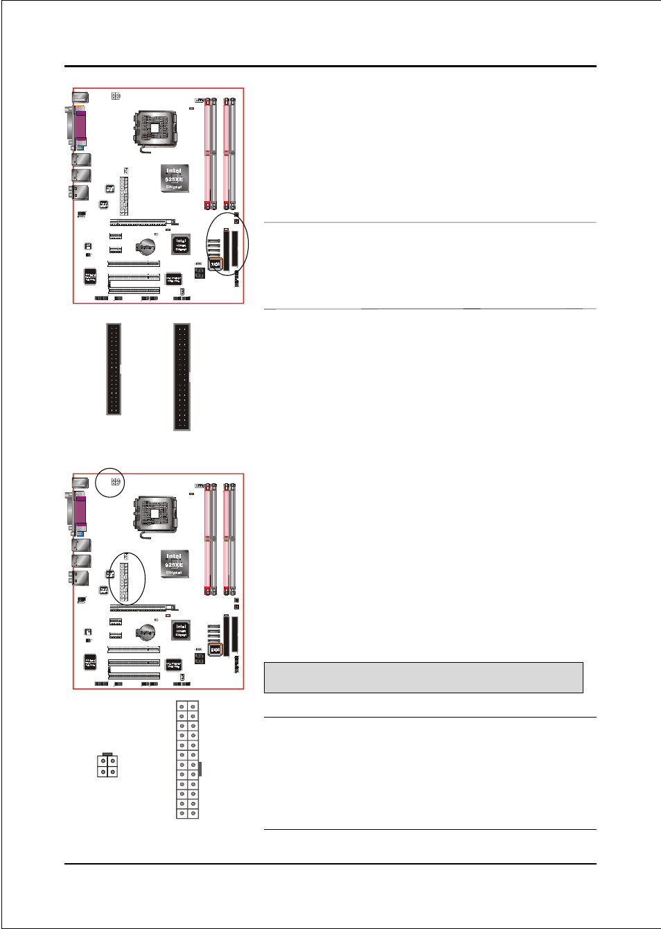
FDD
: Floppy Controller Connector
IDE1: ATA-66/100 IDE Connector
Supports up to 2 IDE devices from embedded IDE
controller .
PW1
IDE1
FDD
PW2
When using two IDE drives, one must be set to
Master mode and the other to Slave mode. Refer to
your disk drive user’s manual for information about
selecting the proper drive switch settings.
PW1: 24-pin ATX Power Connector
PW2: 4-pin ATX12V Power Connector
The mainboard is equipped with a standard 24-pin
ATX main power connector and a 4-pin +12V
power connector for connecting an ATX12V
power supply. The plugs of the power cables are
designed to fit in only one orientation. Insert the
plugs into the connectors until they fit in place.
1
3
1
-12V
3.3V
Ground
+5V
PS-ON
+5V
-5V
PW-OK
+5V
5VSB
+5V
+5V
Ground
+12V
+12V
3.3V
+12V
+12V
23
11
4
2
3.3V
3.3V
Ground
Ground
Ground
Ground
Ground
Ground
Ground
Ground
24
PW1
PW2
The board requires a minimum of 350 Watt power
supply to operate. Your system configuration (amount
of memory, add-in cards, peripherals, etc.) may
exceed this minimum power requirement. To ensure
that adequate power, use a 400 Watt or greater power
supply.
IDE3
Caution:
The PW1 and PW2 Power Connector must be used simultaneously .
40
39
2
1
IDE1
34
33
2
1
FDD