Connectors, Installation instructions – Motorola MVME197LE User Manual
Page 26
Hardware Preparation and Installation
2-6
User’s Manual
2
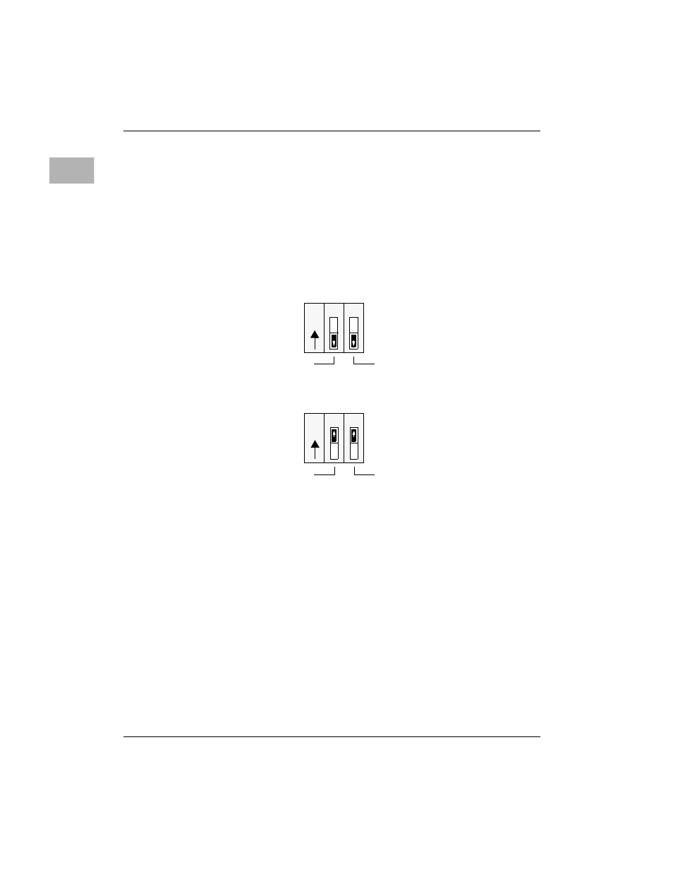
Configuration Switch S6: Serial Port 4 Clock Select (S6-1, S6-2)
Serial port 4 can be configured to use clock signals provided by the RTXC4 and
TRXC4 signal lines. Switch segments S6-1 and S6-2 on the MVME197LE
configures serial port 4 to drive or receive TRXC4 and RTXC4, respectively.
Factory configuration is with serial port 4 set to receive both signals (open).
The remaining configuration of the clock lines is accomplished by using the
Serial Port 4 Clock Configuration Select header on the MVME712M transition
module. Refer to the MVME712M Transition Module and P2 Adapter Board
User’s Manual for configuration of that header.
Connectors
The MVME197LE has two 64-position DIN connectors: P1 and P2. Connector
P1 rows A, B, C, and connector P2 row B provide the VMEbus interconnection.
Connector P2 rows A and C provide the interconnect to the SCSI bus, the serial
ports, the Ethernet interface, and the Centronics printer. There is a 249-pin
mezzanine connector (J2) with the MC88110 bus interface. This mezzanine
connector is for MVME197LE module expansion. There is also a 20-pin
general purpose connector (J1) which provides the interconnect to the LEDs
and the reset and abort signals. Refer to the SIMVME197LE Single Board
Computer Support Information manual for detailed signal descriptions.
Installation Instructions
The following sections discuss installation of the MVME197LE into a VME
chassis, and system considerations. Ensure that the BOOT ROM device is
installed. Ensure that all switches are configured as desired.
Switch S6
Receive TRXC4
Receive RTXC4
(FACTORY CONFIGURATION)
Switch S6
Drive TRXC4
Drive RTXCC4
1
2
1
2
O
N
O
N
CLOSED
OPEN
CLOSED
OPEN