Configuration switches, Configuration switch s1: general information – Motorola MVME197LE User Manual
Page 24
Hardware Preparation and Installation
2-4
User’s Manual
2
Configuration Switches
The location of the switches, connectors, and LED indicators on the
MVME197LE is illustrated in Figure 2-1. The MVME197LE has been factory
tested and is shipped with factory switch settings that are described in the
following sections. The MVME197LE operates with its required and factory-
installed Debug Monitor, MVME197Bug (197Bug), with these factory switch
setting.
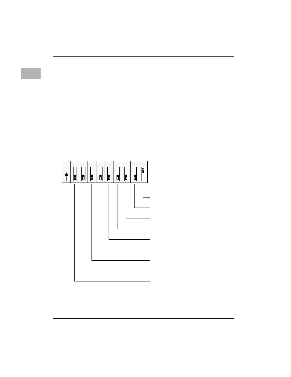
Configuration Switch S1: General Information
Switch S1 is a bank of nine two-way switch segments. The following
illustration shows the factory configuration of switch S1. The bit values are
read as a one when the switch is
OFF
(open), and as a zero when the switch is
ON
(closed). The default value for switch S1 is shown below.
Switch S1
System Controller (SCON)
General Purpose Input 7 (GPI7)
General Purpose Input 6 (GPI6)
General Purpose Input 5 (GPI5)
General Purpose Input 4 (GPI4)
General Purpose Input 3 (GPI3)
General Purpose Input 2 (GPI2)
General Purpose Input 1 (GPI1)
General Purpose Input 0 (GPI0)
(FACTORY CONFIGURATION)
1
O
N
2
3
4
5
6
7
8
9
CLOSED
OPEN