Cdvsc7 & cdv7 series gas fireplace, Electrical installation remote wall switch, Optional dc remote systems – Monessen Hearth CDVR33N/PV7;N/PE7;N/PSC7 User Manual
Page 30
CDVSC7 & CDV7 Series Gas Fireplace
30
69D3011
ON
OFF
OPTIONAL REMOTE
WALL SWITCH
ON
OFF
OPTIONAL REMOTE
CONTROL RECEIVER
PILOT
HI
LO
ON
OFF
TH
TP
TH/TP
ON
OFF
RS
FP1980
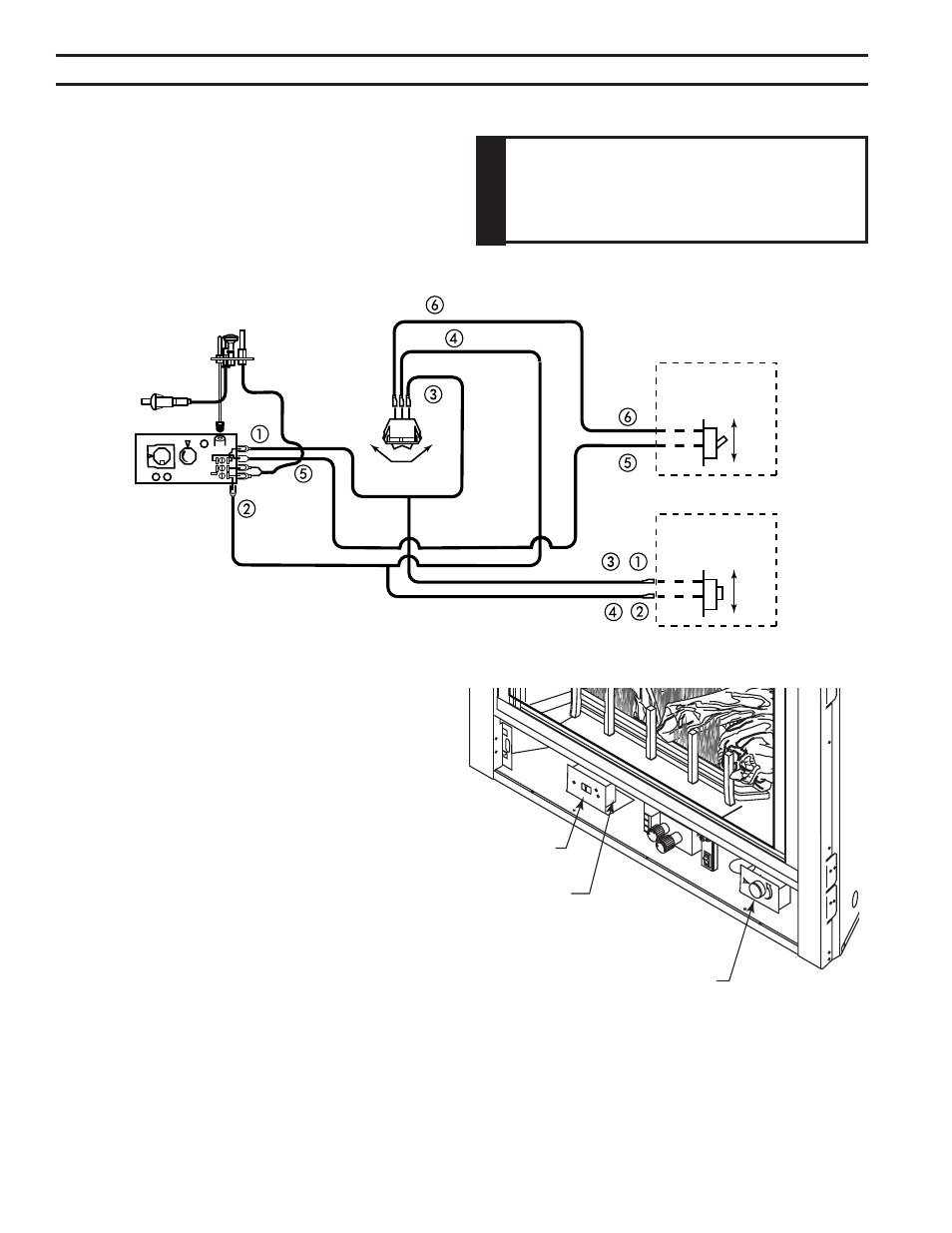
Dv wiring diagram
ReMoTe wall MounTeD SwITCh
A remote wall switch and up to fifteen (15) feet of 18 Ga. wire
may be used with this appliance. Attach the wall switch in a
junction box at the desired location on the wall. Figure 43. Do
not extend beyond the wall switch wire length provided.
noTe: Extended lengths of wire may cause the fireplace not
to function properly. Longer length of wire is permitted if the
wire is made out of larger gauge (diameter) wire. Always check with local code.
Figure 43 -
Wiring Diagram for Wall Switch
eleCTRICal InSTallaTIon
ReMoTe wall SwITCh
Position the wall switch. Do not extend beyond the 15 feet
of wire.
opTIonal DC ReMoTe SySTeMS
See section entitled Hearth Mount in the Millivolt hand held
remote instructions supplied with the remote.
1. Using a flat head screw driver, bend the “remote” tabs
up from the bottom of the fireplace. Figure 44
. Follow the instructions on remote control to snap the
remote cover plate to the remote receiver
3. Connect the wire terminal from the remote receiver.
Figure 43
4. Use the screws that came with the remote control to
mount the remote receiver cover to the bent up “remote”
tabs. Figure 44
w
a
R
n
In
G
Do not connect wall switch to (110 V)
circuit.
FP2284a
CDV7 controls
Remote Control
Receiver
Figure 44 -
Optional Control Location
'Remote' Tabs
FP84a
Blower Speed
Control