Cdvsc7 & cdv7 series gas fireplace – Monessen Hearth CDVR33N/PV7;N/PE7;N/PSC7 User Manual
Page 22
CDVSC7 & CDV7 Series Gas Fireplace
69D3011
VenTInG InSTallaTIon
VeRTICal SIDewall InSTallaTIon -
TwIST loCK pIpe
Step 1
Locate vent opening on the wall. It may be necessary to
first position the fireplace and measure to obtain hole lo-
cation. Depending on whether the wall is combustible or
noncombustible, cut opening to size. Figure 26 (For com-
bustible walls first frame in opening.)
noTe: When using flex vent, the opening will have to be
measured according to the 1/” (13 mm) rise in 1” (305
mm) vent run.
Combustible walls: Cut a 9B\,”H x 9%\,”W (44 x 44 mm)
hole through the exterior wall and frame as shown. Figure
26
noncombustible walls: Hole opening must be 7Z\x” (191
mm) in diameter.
VO584-100
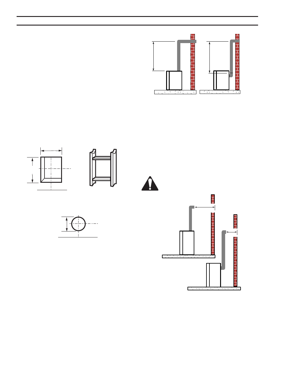
Vent Opening
2/99 djt
Vent opening for Combustible walls
9B\,”
(44 mm)
Fireplace Hearth
Framing Detail
opening for noncombustible wall
7Z\x”
(190 mm)
Fireplace Hearth
FP93
Figure 26 -
Locate Vent Opening on Wall
9B\,”
(44 mm)
Step 2
Secure firestop to the inside frame, center in the 9B\," x
9B\," vent opening.
Step 3
Place fireplace into position. Measure the vertical height
(X) required from the base of the flue collars to the center
of the wall opening. Figure 27
X
X
FP1181
Figure 27 -
Vertical Height Requirements
Step 4
Using appropriate length of pipe section(s) attach to fire-
place with three (3) screws. Follow with the installation of
the inner and outer elbow, again secure joints with three
(3) sheet metal screws.
Step 5
Measure the horizontal length requirement including a ”
(51 mm) overlap, i.e. from the elbow to the outside wall
face plus ” (51 mm) (or the distance required if installing
a second 90° elbow). Figure 28
always install horizontal venting on a level
plane.
X
X
FP118
Figure 28 -
Horizontal Length Requirement