Fp2140 signature command wiring, Khldv series gas fireplace, Wa rn in g – Monessen Hearth KHLDV400 User Manual
Page 31: Command center wall installation, Caut io n
73D0024
31
KHLDV Series Gas Fireplace
COMMAND
CENTER
4-AA BATTERY
COMPARTMENT
MASTER
SWTICH
TO JUNCTION BOX
IN FIREPLACE
CONVERSION
NG/LP
RF RECEIVER
ON/OFF BUTTON
WHITE
BLACK
WHITE
BLACK
BLACK
WHITE
GREEN
CONNECTOR
PIN TO CONTROL BOX
AC BOX
{
OPTIONAL
BLOWER
PLUG IN
CONNECT
OR
ON/HI
OFF/LO
LED
IGNITER/SPARKER
SENSING
RED/THERMOPILE
BLACK/THERMOPILE
PILOT GAS TUBING
PILOT
CONTROL BOX
PLUG IN CONNECTOR
CONTROL BOX TO COMMAND CENTER
PLUG IN CONNECTOR
STEPPER MOTOR TO
CONTROL BOX
PLUG IN CONNECTOR
CONTROL BOX TO
SOLENOID
DC POWER/GREEN
VALVE
GROUND
INPUT 300 WATT MAX EACH
GAS IN
GAS OUT
REAR BURNER
SOLENOID
BACK
LIGHT
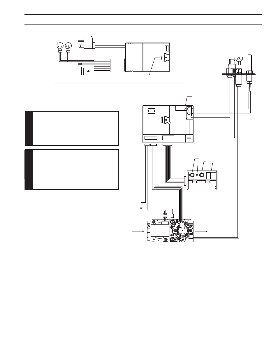
fp2140
Signature command wiring
SIGnature cOMManD OptIOnaL waLL cOMManD center and BLOwer SySteM
Electrical connections should only be
performed by a qualified, licensed electri-
cian. Main power supply must be turned
off before connecting fans to the main
electrical power supply or performing
service.
caut
IO
n
Figure 41 -
Signature Command Wiring Diagram
w
a
rn
In
G
Before installing the blower, turn off the
fireplace and allow to cool. Only a quali-
fied service person should service and
repair the fireplace. A qualified service
person should connect and disconnect
the fireplace to gas supply. Follow all
local codes.
cOMManD center waLL InStaLLatIOn
The Command Center may be mounted on the wall with the use of the SCSWEK Kit. (15' cable, junction
box and wall cover).
Mount the junction box provided at the desired location on the wall. Do not extend beyond the 15' wire
cable provided.
Route wire from junction box to lower control area at bottom of fireplace. Unplug the 12' cable from control
box and command center. Plug the 15' extension cable into the control box. Remove command center
from the fireplace and plug the other end of the extension cable into the command center. Snap on wall
cover provided and screw to junction box.