Chapter 2. connecting, 7$3cbdlqbofm, 57cbdlqbofm – MITSUBISHI ELECTRIC WD-62526 User Manual
Page 27: 3'4qmjuufs, Odpnjoh $bcmf"oufoob
Chapter 2. Connecting
27
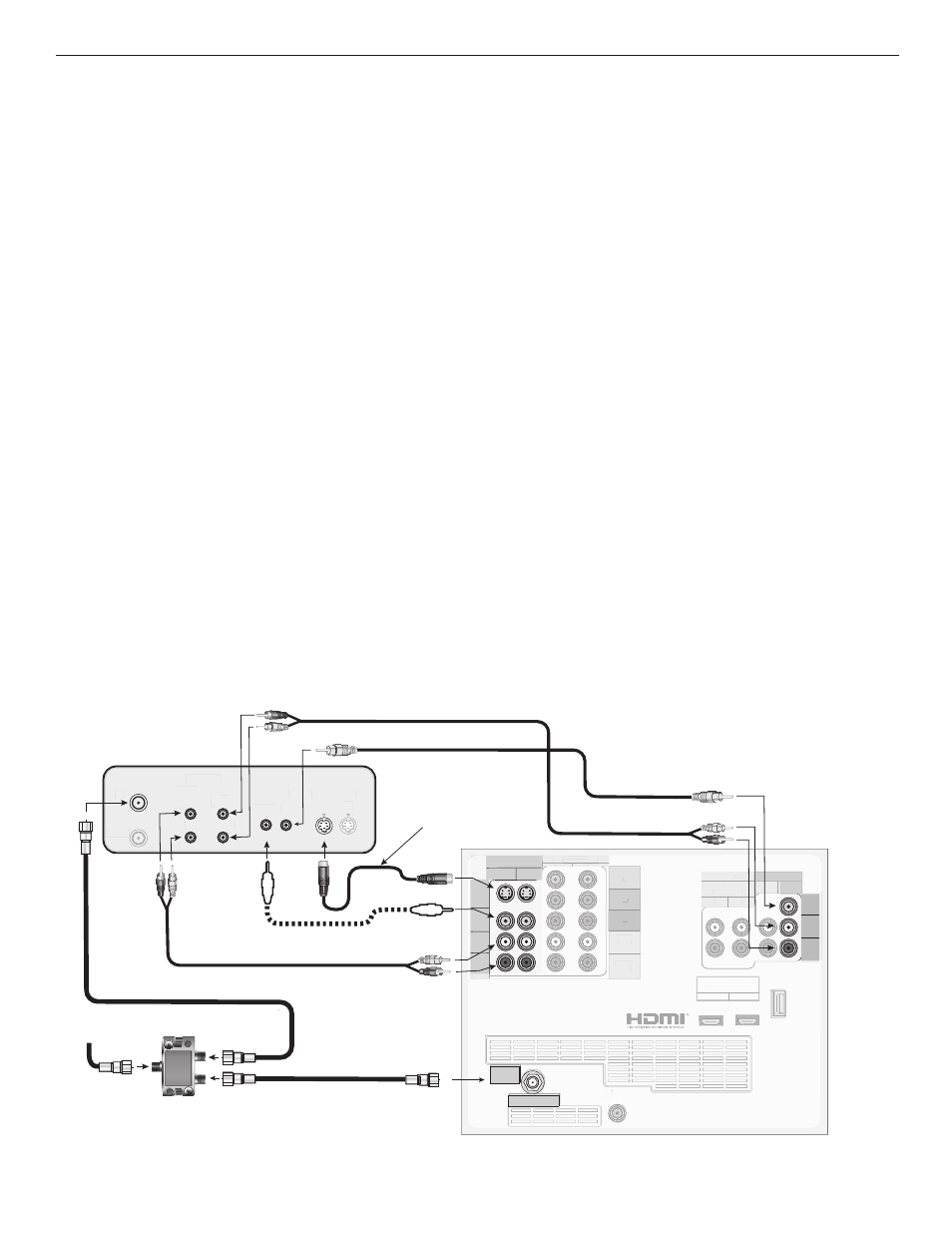
VCR and an Antenna or Wall Outlet
Cable (Audio & Video)
Figure 7
A two-way RF splitter, 3 coaxial cables, right and left audio
cables, and an S-Video or composite video cable are required.
These are not included with the TV but are available at most
electronics stores.
1. Connect the incoming cable or Antenna to IN on the
RF splitter.
2. Connect one coaxial cable from OUT on the RF splitter
to ANTENNA IN on the VCR back panel.
3. Connect one coaxial cable from OUT on the RF splitter
to ANT 1 on the TV back panel.
4. To use the TV speakers with the VCR, connect a set of
audio cables from AUDIO OUT on the VCR back panel
to INPUT AUDIO-LEFT (MONO) and AUDIO-RIGHT
on the TV back panel. Connect the red cable to the
R (right) channel and the white cable to the L (left)
channel. If your VCR is mono (non-stereo), connect
only the white (left) cable.
Figure 7. Connecting a VCR to an Antenna or Wall Outlet Cable
5. Connect either an S-Video or Composite Video
cable from VIDEO OUT on the VCR back panel
to INPUT S-VIDEO/VIDEO on the TV back panel.
Connect only one type of video cable. S-Video is
recommended, if available.
Optional Additional Connections
6. To record from the TV tuner to the VCR, make the
following additional connections. These connec-
tions allow you to record high-definition program-
ming, downconverted to standard definition, on an
analog VCR.
a. Connect a set of audio cables from AUDIO IN
on the VCR back panel to RECORD OUTPUT/
AUDIO-LEFT (MONO) and AUDIO-RIGHT on the
TV back panel. Connect the red cable to the R
(right) channel and the white cable to the L (left)
channel.
b. Connect a video cable (composite video) from
VIDEO IN on the VCR back panel to RECORD
OUTPUT/VIDEO on the TV back panel.
COMPONENT
YPbPr (480i/480p/720p/1080i)
INPUT
1
2
-VIDEO
LEFT/
DTV/CABLE/
VHF/UHF
DIGITAL
AUDIO
OUTPUT
1
2
Y
Pb
Pr
AUDIO-
LEFT/
(MONO)
AUDIO-
RIGHT
OUTPUT
AUDIO
OUTPUT
RECORD
OUTPUT
DVI
Analog Audio
1
2
VIDEO
AUDIO-
LEFT/
(MONO)
AUDIO-
RIGHT
SERVICE
PORT
MONITORLINK™/HDMI
VIDEO 480i/480p/720p/1080i
AUDIO PCM LINEAR
1
2
INPUT
ANT 1
VIDEO
AUDIO-
LEFT/
(MONO)
AUDIO-
RIGHT
E
S-VIDEO
COMPONENT
YPbPr (480i/480p/720p/1080i)
DTV
TT /
V
V CA
C
C BLE/
VHF/
FF UHF
DIGITA
TT L
AUDIO
OUTPUT
1
2
Y
Pb
Pr
AUDIO-
LEFT/
(MONO)
AUDIO-
RIGHT
AUDIO
OUTPUT
DVI
Analog Audio
1
2
SERVICE
PORT
MONITORLINK™/HDMI
VIDEO 480i/480p/720p/1080i
AUDIO PCM LINEAR
1
2
INPUT
ANT 1
ANT 1
DTV/CABLE/
VHF/UHF
"/5&//"
065
065
065
065
*/
*/
*/
*/
3
3
-
-.0/0
"6%*0
7*%&0
47*%&0
"/5&//"
"/5&//"
065
065
065
065
065
065
065
065
*/
*/
*/
*/
*/
*/
*/
*/
3
3
3
3
-
-
-.0/0
-.0/0
"6%*0
"6%*0
7*%&0
7*%&0
47*%&0
47*%&0
065
*/
*/
3
3
-
-.0/0
"6%*0
065
065 */
7*%&0
47*%&0
*/
065
065
5808
"
:41-*55&3
3'4QMJUUFS
7$3CBDLQBOFM
B
B
C
C
"UUBDIPOMZPOFUZQFPG
WJEFPDBCMF4WJEFP
SFDPNNFOEFEJG
BWBJMBCMF
7JEFPDBCMF
DPNQPTJUFWJEFP
4WJEFPDBCMF
57CBDLQBOFM
*ODPNJOH
$BCMF"OUFOOB