Appendix b: connections, Xlr connectors, 1/4" trs phone plugs and jacks – MACKIE PORTABLE RECORDING PREAMP User Manual
Page 27: 1/4" ts phone plugs and jacks, Rca plugs and jacks, Unbalancing a line, Owner’ s manual, Balanced mono, Stereo headphones, Owner’s manual
7
Owner’s Manual
Owner’
s Manual
Appendix B: Connections
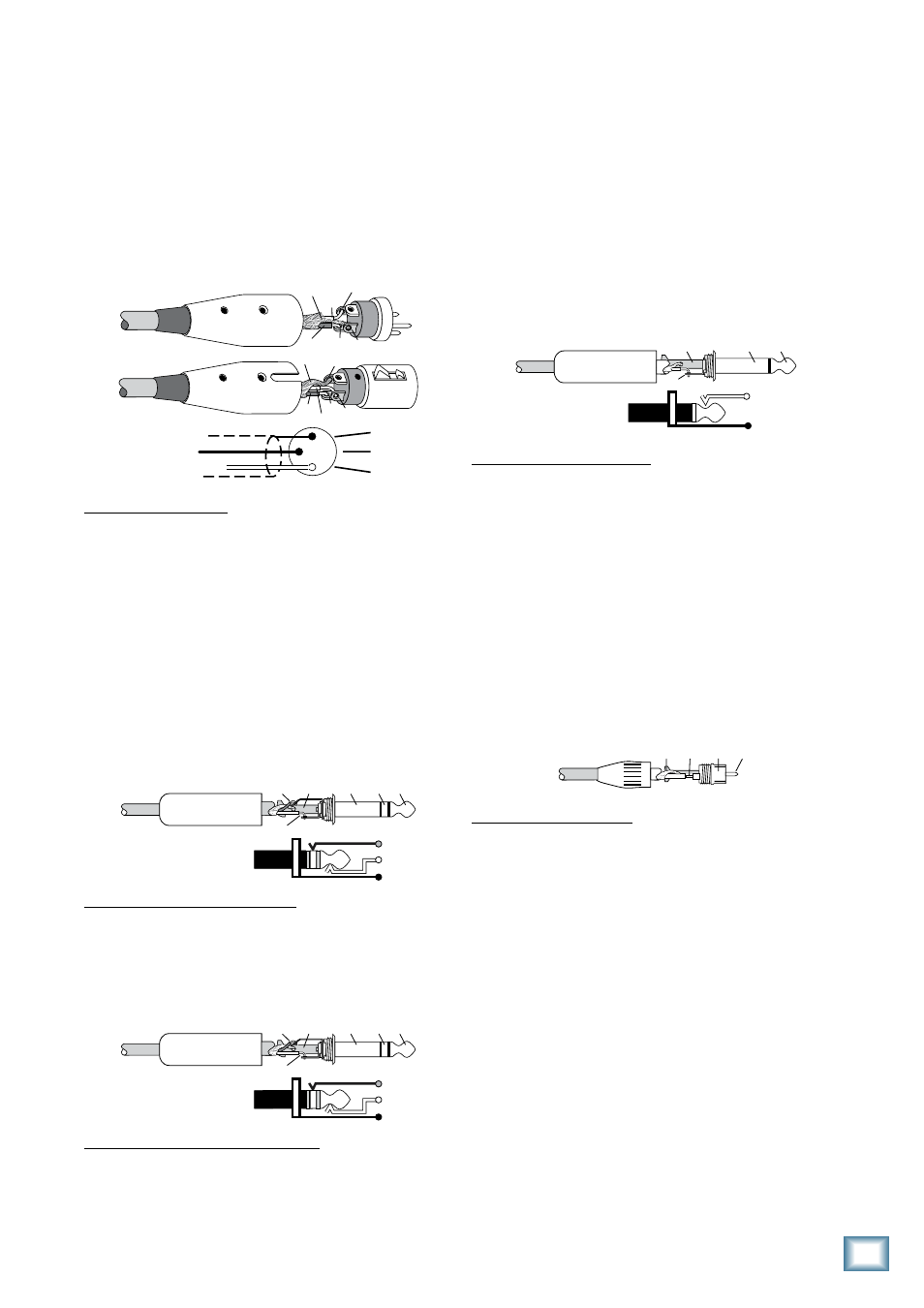
XLR Connectors
Channels 1-4 accept 3-pin male XLR connectors on
the Neutrik combo inputs. They are wired as follows,
according to standards specified by the AES (Audio
Engineering Society).
2
2
3
1
1
SHIELD
COLD
HOT
SHIELD
COLD
HOT
3
SHIELD
COLD
HOT
3
2
1
XLR Balanced Wiring:
Pin 1 = Shield
Pin 2 = Hot (+)
Pin 3 = Cold (–)
1/4" TRS Phone Plugs and Jacks
“TRS” stands for Tip-Ring-Sleeve, the three connection
points available on a stereo 1/4" or balanced phone
jack or plug. TRS jacks and plugs are used for balanced
signals and stereo headphones.
Balanced Mono
SLEEVE
TIP
SLEEVE
TIP
RING
RING
TIP
SLEEVE
RING
1/4" TRS Balanced Mono Wiring:
Sleeve = Shield
Tip = Hot (+)
Ring = Cold (–)
Stereo Headphones
SLEEVE
TIP
SLEEVE
TIP
RING
RING
TIP
SLEEVE
RING
1/4" TRS Stereo Unbalanced Wiring:
Sleeve = Shield
Tip = Left
Ring = Right
1/4" TS Phone Plugs and Jacks
“TS” stands for Tip-Sleeve, the two connection points
available on a mono 1/4" phone jack or plug. They are
used for unbalanced signals like the high-impedance
instrument inputs on the Onyx Satellite.
SLEEVE
TIP
TIP
SLEEVE
TIP
SLEEVE
1/4" TS Unbalanced Wiring:
Sleeve = Shield
Tip = Hot (+)
RCA Plugs and Jacks
RCA-type plugs (also known as phono plugs) and jacks
are often used in home stereo and video equipment, and
to make S/PDIF connections on consumer digital audio
devices (they are not used on the Onyx Satellite). They
are unbalanced and electrically equivalent to a 1/4" TS
phone plug.
TIP
SLEEVE
TIP
SLEEVE
RCA Unbalanced Wiring:
Sleeve = Shield
Tip = Hot (+)
Unbalancing a Line
In most studio, stage, and sound reinforcement situ-
ations, there is a combination of balanced and unbal-
anced inputs and outputs on the various pieces of
equipment. This usually will not be a problem in making
connections.
• When connecting a balanced output to an unbal-
anced input, be sure the signal high (hot) connec-
tions are wired to each other, and that the balanced
signal low (cold) goes to the ground (earth)
connection at the unbalanced input. In most cases,
the balanced ground (earth) will also be connected
to the ground (earth) at the unbalanced input. If
there are ground-loop problems, this connection
may be left disconnected at the balanced end.